8
Note: This section applies to both B127-1A1-MM-DD and B127-1A1-SM-DD
extender kits.
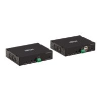
The extender kits provide one of the following functions via DIP switch
settings:
• USB 1.1 – One Micro-USB input at transmitter, dual USB-A outputs at
receiver
• Bi-Directional IR –Dual 3.5 mm jacks at both the transmitter and
receiver
• RS-232 – One 3-pin phoenix connector at both the transmitter and
receiver
DIP Switch Positions Function Selection
1 (Up), 2 (Up) IR Function
1 (Up), 2 (Down) USB Function
1 (Down), 2 (Down) RS-232 Function
DIP Switch Settings
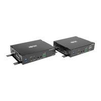
Standard Extender Kit Installation
8
Turn on the power to the DisplayPort source. The OUTPUT (orange)
LED on the local unit will illuminate to indicate a signal has been
received from the source.
9
The (orange) LED will illuminate on both local transmitter and remote
receiver units to indicate a signal has been received from source to
display. The screen should now display on the connected monitor.
19-06-088-933976.indb 8 8/9/2019 9:48:10 AM
 Loading...