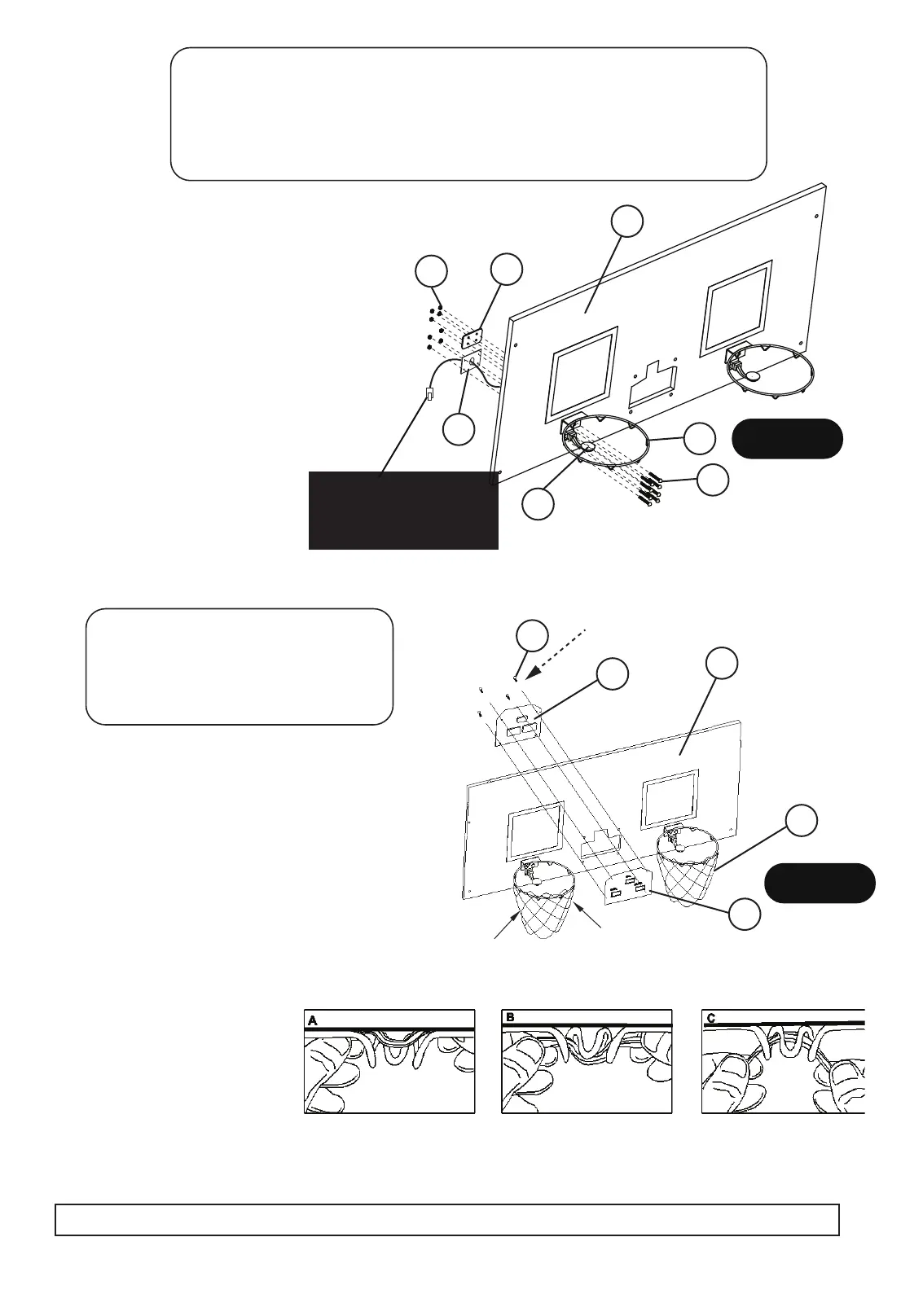
STEP 6
PARTS REQUIRED:
2 pcs - #15 Mechanical Scoring Arm 16 pcs - #23 M6 x 20 mm Bolt
2 pcs - #17 Rim 16 pcs - #27 M6 Lock Nut
2 pcs - #18 Rim Support Plate 1 pc - #31 Wrench
1 pc - #21 Backboard 1 pc - #36 Allen Wrench
2 pcs - #35 Mechanical Arm Support Plate
Attach Rims (#17) and Rim Support
Plates (#18) to the Backboard (#21)
using Bolts (#23) and Lock Nuts (#27)
as shown in FIGURE 6.
Attach Mechanical Scoring Arms (#15)
and Mechanical Scoring Arm Support
Plates (#35) to the Backboard (#21)
using Bolts (#23) and Lock Nuts (#27)
as shown in FIGURE 6.
Use Wrench (#31) and Allen
Wrench (#36) tighten all Bolts.
15
17
18
35
21
23
27
FIGURE 6
NOTE:
Mechanical Scoring
Snug tighten only – overtightening could
strip the screw or break the #30 face plate
Arm (#15)
sensor plug must pass through
Backboard (#21) and Mechanical
Scoring Arm Support Plate (#35)
PARTS REQUIRED:
1 pc - #14 Electronic Scorer
2 pcs - #20 Rim Net
4 pcs - #29 3.5 x 10 mm Screw
1 pc - #30 Electronic Scorer Face Plate
STEP 7
Attach Electronic Scorer Face Plate to the
Backboard (#21) and connect with Electronic
Scorer (#14) using Screws (#29)
as shown in FIGURE 7.
Loop the Rim Net (#20) through the ram horns
on the Rims (#17) as shown in FIGURE 7.
FIGURE 7
14
29
20
30
21
8
For Customer Service Call 1-888-996-2729
© 2017 Escalade S por t s
All Rights Reserved
Note: This is a special rim net
designed to avoid entanglement
with the mechanical scoring arm.`
Net does have a
top and bottom,
The long loops go
to the top.
Please study each diagram closely and read all assembly notes to insure correct assembly