Operating Manual – IDE 30 / 50 / 60
EN
B - 5
09. Installation and commissioning
• Check that the scope of delivery of your oil heat-
ing unit is complete. If an accessory part is miss-
ing, please contact the Trotec customer service or
the specialist dealer from whom you purchased
the device.
• Check the oil heating unit and its connection parts
for possible damages.
• Mount the support/the handle and the wheels to
the oil heating unit.
• Make sure to comply with the requirements de-
scribed in the chapter “Installation conditions”.
• Correctly connect the exhaust system of the device
to a chimney or an external wall as shown in the
chapter “Exhaust system”.
• Fill the heating oil into the tank with the device
switched off and cooled down.
• Inspect the device prior to commissioning and
check it regularly for its proper condition during
operation.
• Make sure that the characteristics of the mains sup-
ply correspond to those indicated on the rating plate.
• Each time before switching on the device, make
sure that the fan can move freely before plugging
the power plug into the mains socket.
• Connect the power supply cable to a properly se-
cured mains socket (230 V / 50 Hz / 10 A). On con-
struction sites, a residual current circuit breaker
must be connected upstream of the mains socket
according to VDE 0100/0105.
The oil heating unit is now ready for operation. Use
the device according to the functions described in
chapter 11 “Functions and operation”.
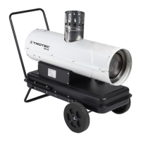
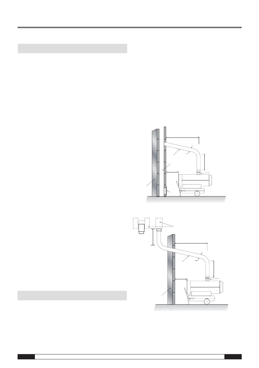
10. Exhaust system
• Before planning the installation of the exhaust sys-
tem, the local chimney sweep must be informed
according to DIN 18160.
m Risk of injury due to intoxication! Improp-
er installation of the exhaust system may
cause health problems. Have the installation
carried out by a specialised craftsman!
• Make sure that an unobstructed and sufficient sup-
ply of combustion air (e. g. by means of ventilation
openings in doors, ceilings, windows, walls or an
ambient air network) is provided.
• Have the exhaust gas values of the burner checked
regularly.
Chimney duct
Wall duct
A min. 2 m 1 Chimney connection
B min. 1 m 2 Wall duct with pipe elbow min. 5°
C as short as possible 3 Chimney - min. internal dimensions 20x20 cm
D ≥ ø 120 mm/150 mm 4 Opening for cleaning with explosion
E min. 1 m protection cap
5 External wall
6 Draft reinforcement, H-shaped
B
1
D
2
C
3
A
5
4
E
6
5
A
C
2
D
B
1
 Loading...