14 Operating Manual – Dehumidifier TTK 75 E EN
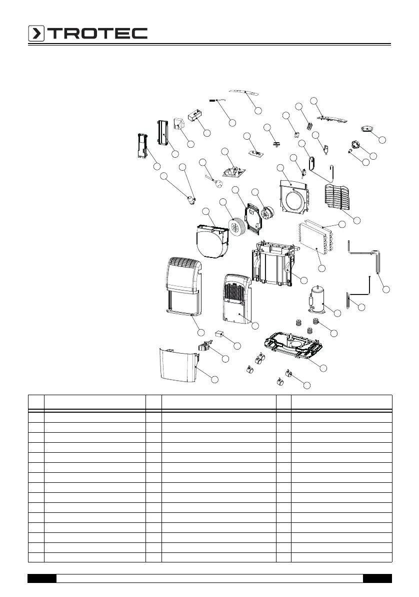
Overview and list of spare parts
No. Spare part No. Spare part No. Spare part
1 Base pan 16 Blower wheel 31 Handle
2 Turning wheel assembly 17 Fan casing 32 Drain bucket
3 Compressor assembly 18 Capacitor (10 μF/450 for compressor (3)) 33 Tank lid
4 Rubber 19 Fix metal 34 Float
5 Suction pipe 20 Power supply cord complete 35 Air filter
6 Discharge pipe 21 Control board 36 Fixture
7 Plate 22 Lamp assembly 37 Cover
8 Evaporator assembly 23 Knob 38 Cover
9 Condenser assembly 24 Capacitor (1 μF/450 for fan motor (14)) 39 Humidity switch
10 Y tube 25 Fix metal 40 Sensor
11 Capillary tube 26 Control plate 41 Control panel
12 Micro switch 27 Front panel
13 Fan tank 28 Rear panel
14 Fan motor 29 Soft cap
15 Strike 30 Plug
1
2
4
34
3
35
36
7
6
5
8
9
12
11
10
25
26
32
33
13
14
15
16
17
20
21
22
23
24
18
19
29
30
27
28
31
37
39
40
41
38
Note!
The position numbers of the spare parts
differ from those describing the posi-
tions of other parts mentioned in this
operating manual.