3 Electrical connection
3.1 General safety notes
DANGER!
Danger of electric shock! Do not touch any live com-
ponents! Electrical equipment carries a dangerous
electrical voltage.
– Only skilled qualified electricians are allowed to
work on the electrical system.
– Switch off the power supply before working on
any electrical equipment.
Observe the VDE guidelines for connection work!
3.2 Potentional equalisation
To prevent ignition sources due to static charging, the
fire damper must be integrated into the potential equali-
sation of the ventilation system.
Execution of potential equalisation (on-site):
Single-wire CU cable 4 mm
2
with ring cable lug.
Connection options for potential equalisation:
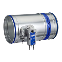
Fire damper with ExMax / RedMax spring return
actuator
– Terminal box to terminal PA
Fire damper with fusible link
– Flange version: fixing screws (M8) on the inside
of the flange, or drilling screw on the flange
– Spigot version: Screw (1) Fig. 3 on release
device
Fig. 3: FKR-EU Potential equalisation connection
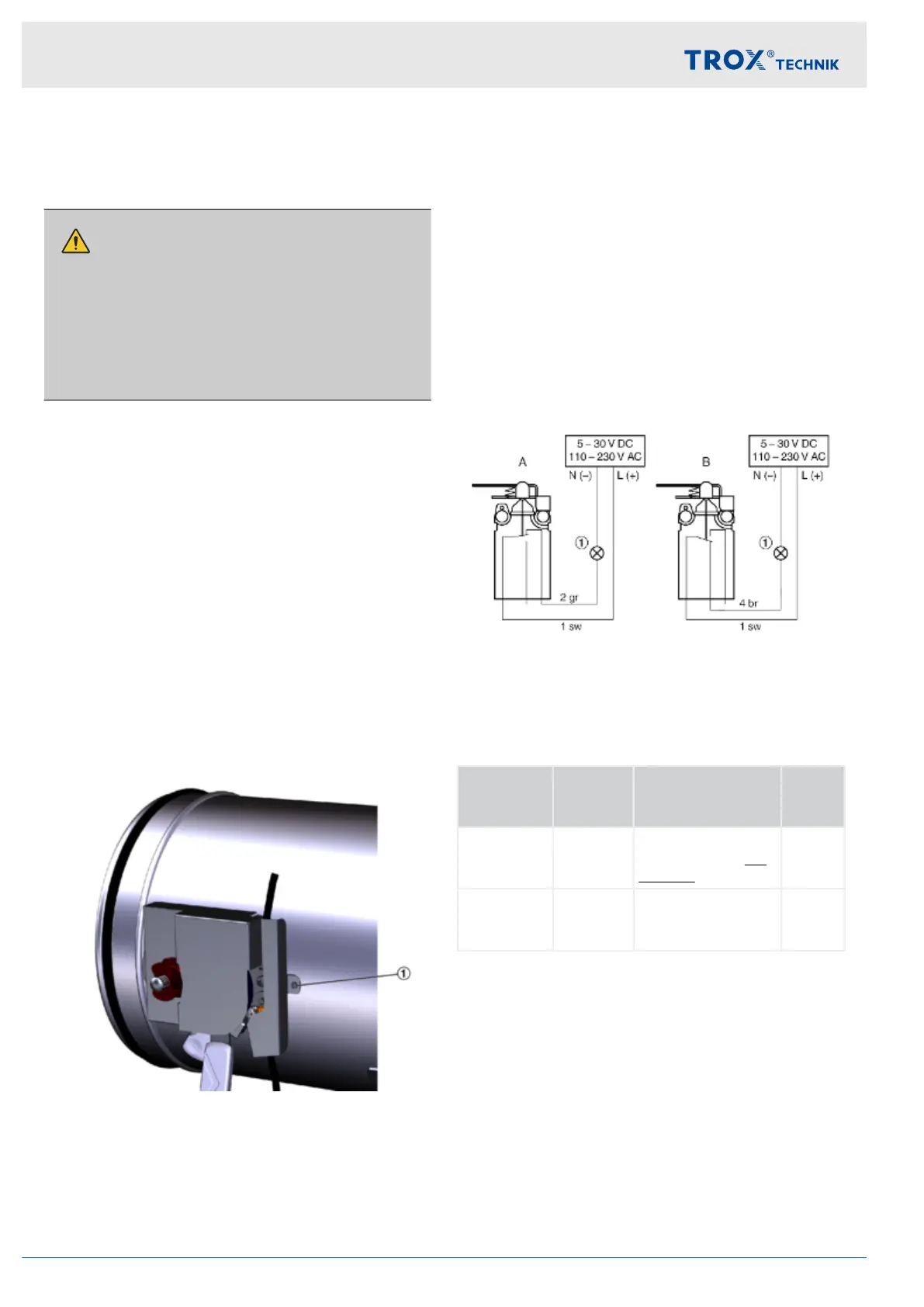
3.3 Ex limit switch for version with
fusible link
Connection of the Ex limit switches acc. to the wiring
example (see figure). The limit switches must be con-
nected in a separately certified casing of a recognised
type of protection according to EN 60079-0.
Indicator lights or relays may be connected as long as
the performance specifications are taken into considera-
tion.
The EX limit switches can be used as "NO normally
open" or "NC normally closed" contacts for signalling.
Connection example Ex limit switch
Fig. 4: Connection example Ex limit switch
1 Indicator light or relay, to be provided by customer
A Connection type NC contact
B Connection type NO contact
Connec-
tion type
Limit
switch
Damper blade Elec-
tric cir-
cuit
A not
actuated
CLOSED or
OPEN position not
reached
closed
B actuated CLOSED or
OPEN position
reached
closed
Electrical connection
Ex limit switch for version with fusible link
Explosion-proof fire damper FKR-EU10