3
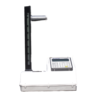
3. The groups of jumpers are marked as
“3411” “3430” or “3440/ 3500” switches.
4. To configure the UBB for operation as a
3401/3411baseboard, only the group of
jumpers marked as 3411 switches need to
remain shorted by means of the jumpers.
Carefully remove all of the jumpers from
the groups marked as 3430 switches and
3440/3500 switches by cutting them with
wire cutters.
5. Locate the groups of jumpers marked S4 and
S6. Leave the jumpers marked 3411. Cut
the jumpers marked 3500/3430.Fig 6b
6. Place one copper grounding spring between
the bottom side of the UBB and the GM
tube holder with the resistors. Ensure the
resistor leads from the GM tube holder
extend through the solder holes of the UBB.
Secure the GM tube holder with the
mounting screws. Solder the resistor leads
to the UBB at GM1 and GM2 points. Fig.6.
7. Slide the metal base plate into the grooves
on the GM tube holder.
8. Secure the UBB to the metal base plate with
the screws taken out.
9. Place the GM tubes into the secured GM
tube holder making sure the end of the GM
tube with springs and nylon spring supports
are the end inserted into this connector.
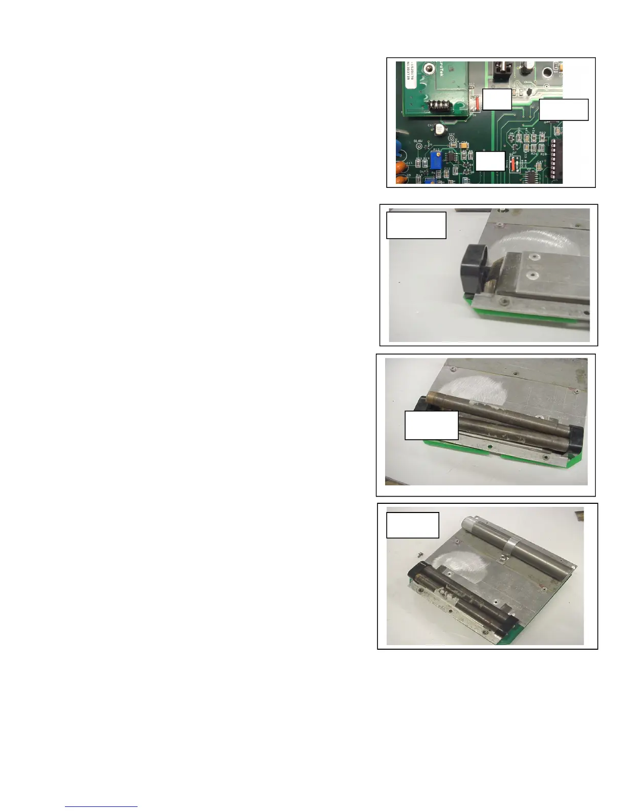
10. Install the other copper ground spring and
GM tube holder by sliding it onto the metal
base plate and securing it to the UBB with
the appropriate screws. Fig. 7 and 8.
11. Reinstall the He3 tube and mounting
bracket. Fig.9.
12. Place the complete assembly back into the
gauge and secure it with the appropriate
screws.
13. Connect the batteries and control board
(front panel) to the UBB.
14. The UBB assembly is now complete and
ready for electrical adjustment and setup.
15. Proceed to Section D.
Fig.7
Fig.8
Fig.9
 Loading...