Section2: Assembly
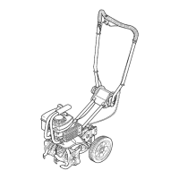
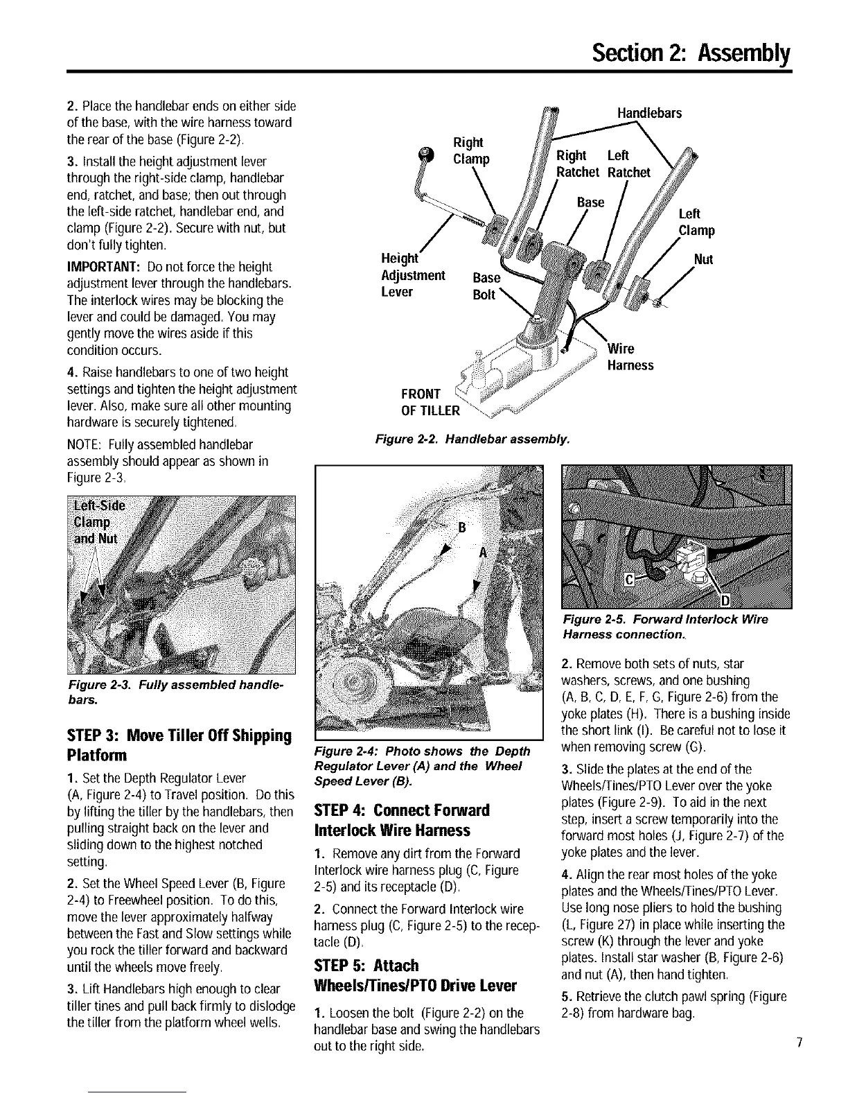
2. Placethe handlebarends on either side
of the base,with the wire harnesstoward
the rear of the base(Figure 2-2).
3. Installthe height adjustment lever
through the right-side clamp, handlebar
end, ratchet, and base;then out through
the left-side ratchet, handlebar end,and
clamp (Figure2-2). Securewith nut, but
don't fully tighten.
IMPORTANT:Do not force the height
adjustment leverthrough the handlebars.
Theinterlock wires may be blocking the
leverand could be damaged.Youmay
gently move thewires aside if this
condition occurs.
4. Raisehandlebars to one of two height
settings and tighten the height adjustment
lever. Also, make sureall other mounting
hardware is securelytightened.
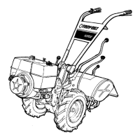
NOTE: Fully assembledhandlebar
assembly should appearas shown in
Figure2-3.
Figure 2-3. Fully assembled handle.
bars.
STEP 3: Move Tiller Off Shipping
Platform
1. Set the Depth Regulator Lever
(A, Figure2-4) to Travel position. Dothis
by lifting the tiller by the handlebars,then
pulling straight back on the lever and
sliding down to the highest notched
setting.
2. Set the WheelSpeedLever (B, Figure
2-4) to Freewheelposition. To do this,
move the leverapproximately halfway
betweenthe Fastand Slow settings while
you rock the tiller forward and backward
until the wheels movefreely.
3. Lift Handlebarshigh enough to clear
tiller tines and pull back firmly to dislodge
the tiller from the platform wheel wells.
Right
Height
Adjustment Base
Lever
FRONT
OFTILLER
Figure 2-2. Handlebar assembly.
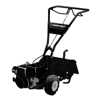
Figure 2.4: Photo shows the Depth
Regulator Lever (,4) and the Wheel
Speed Lever (B).
STEP 4: Connect Forward
Interlock Wire Harness
I. Removeany dirt from the Forward
Interlock wire harness plug (C, Figure
2-6) and its receptacle(D).
2. Connectthe Forward Interlock wire
harness plug (C, Figure2-6) to the recep-
tacle (D).
STEP 5: Attach
Wheels/Tines/PTO Drive Lever
I. Loosenthe bolt (Figure 2-2) on the
handlebar baseand swing the handlebars
out to the right side.
Handlebars
Left
Clamp
Nut
Wire
Harness
Figure 2.5. Forward Interlock Wire
Harness connection.
2. Removeboth sets of nuts, star
washers, screws, and one bushing
(A, B,C, D, E, F,G, Figure2-6) from the
yoke plates (H). Thereis a bushing inside
the short link (I). Becareful not to lose it
when removing screw (G).
3. Slide the plates atthe end of the
Wheels/Tines/PTOLeverover the yoke
plates (Figure2-9). To aid in the next
step,insert a screw temporarily into the
forward most holes (J, Figure2-7) of the
yoke plates and the lever.
4. Align the rear most holesof theyoke
platesand the WheelslTineslPTOLever.
Uselong nosepliers to hold the bushing
(L, Figure27) in place while inserting the
screw (K) through the lever and yoke
plates.Install star washer (B, Figure 2-6)
andnut (A), then handtighten.
5. Retrievethe clutch pawl spring (Figure
2-8) from hardwarebag.
 Loading...