!1
Assembly
To prevent personal injury or property
damage, do not start the engine until
all assembly steps are complete and
you have read and understand the
safety andoperating instructionsin this
manual.
Introduction
Carefullyfollow these assembly steps to
correctly prepareyour tiller for use. It is
recommendedthat you readthis Section
in itsentirety before beginning assembly.
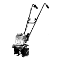
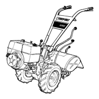
NOTE:Varioustiller models are presented
in this Manual. Useonly the information
appropriatefor your tiller model,
Inspect Unit
Inspectthe unit and carton for damage
immediatelyafter delivery, Contactthe
carrier (trucking company) if you find or
suspect damage. Inform them of the
damageand request instructionsfor filing
a claim. To protect your rights, put your
claim in writing and mail a copy to the
carrier within 15 days after the unit has
beendelivered. Contact usat the Factory
if you needassistance in this matter.
STEP 1: Unpacking Instructions
NOTE:Do not severelybend any of the
control cables on the unit.
I. The tiller is heavy. Do not attempt to
remove it from the shipping platform until
instructed to do so in these Assembly
steps.
2. Removeall unassembled parts from
the carton. Thehardware bag is included
in your literature packaging.
3. If you orderedan Electric Start Tiller,
remove the hardwarebag from under the
battery clamp (A,Figure 2-16).
4. Checkthat you havethe items listed
below (contact your local dealeror the
6
Factory if anyitems are missing or
damaged).
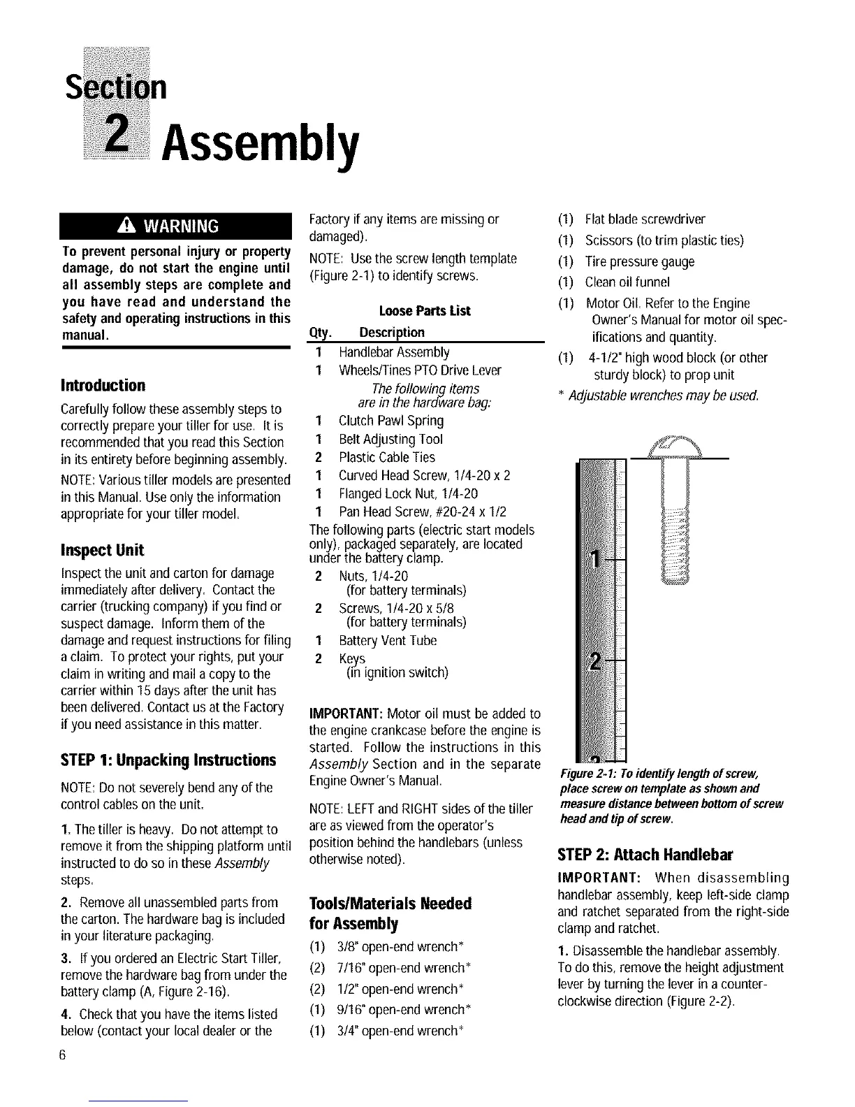
NOTE: Usethe screw lengthtemplate
(Figure2-1) to identify screws.
LoosePartsList
Qty. Description
1 HandlebarAssembly
1 Wheels/TinesPTODrive Lever
Thefollowing items
are in the hard-warebag:
1 Clutch PawlSpring
1 BeltAdJustingTool
2 PlasticCableTies
1 Curved HeadScrew, 1/4-20 x 2
1 FlangedLock Nut, 1/4-20
1 PanHeadScrew, #20-24 x 1/2
Thefollowing parts (electric start models
only/),packagedseparately,are located
under the batteryclamp,
2 Nuts, I/4-20
(for battery terminals)
2 Screws, I14-20 x 518
(for battery terminals)
1 BatteryVent Tube
2 Keys
(Fnignition switch)
IMPORTANT:Motor oil must be added to
the engine crankcase beforethe engine is
started. Follow the instructions in this
Assembly Section and in the separate
EngineOwner's Manual.
NOTE:LEFTand RIGHTsides of thetiller
are asviewedfrom the operator's
position behind the handlebars(unless
otherwise noted).
Tools/Materials Needed
for Assembly
(1) 3/8"open-end wrench*
(2) 7/16"open-end wrench*
(2) 1/2"open-end wrench*
(1) 9/16°open-end wrench*
(1) 3/4"open-end wrench*
(1) Flatbladescrewdriver
(1) Scissors (to trim plastic ties)
(1) Tire pressure gauge
(1) Cleanoil funnel
(1) Motor Oil. Referto the Engine
Owner's Manualfor motor oil spec-
ifications and quantity.
(1) 4-1/2" high wood block (or other
sturdy block) to prop unit
* Adjustable wrenchesmay be used.
Figure2. I: Toidentify lengthof screw,
place screwon templateas shownand
measuredistance betweenbottomof screw
headand tip of screw.
STEP 2: Attach Handlebar
IMPORTANT: When disassembling
handlebar assembly, keep left-side clamp
and ratchet separatedfrom the right-side
clamp and ratchet.
I. Disassemblethe handlebarassembly.
To do this, remove the height adjustment
leverby turning the leverin acounter-
clockwise direction (Figure2-2).



 To Next Page