8
SPECIFICATIONS
Approximate Unit Weight (without the battery). . . . . . . . . . . . . . . . . . . . . . . . . . . . . . . . . . . . . . . . . . . . . . . . . . . . . . . . 7.5 - 8.5 lbs. (3.4 - 3.9 kg)
Trimmer Mechanism . . . . . . . . . . . . . . . . . . . . . . . . . . . . . . . . . . . . . . . . . . . . . . . . . . . . . . . . . . . . . . . . . . . . . . . . . . . . . . . . . . . . . . . Bump Head
Trimming Line Diameter. . . . . . . . . . . . . . . . . . . . . . . . . . . . . . . . . . . . . . . . . . . . . . . . . . . . . . . . . . . . . . . . . 0.080 to 0.090 in. (2.03 to 2.29 mm)*
Cutting Path Diameter. . . . . . . . . . . . . . . . . . . . . . . . . . . . . . . . . . . . . . . . . . . . . . . . . . . . . . . . . . . . . . . . . . . . . . . . . . . . . . . . . . . 16 in. (40.6 cm)
Battery Type (Model 4144) . . . . . . . . . . . . . . . . . . . . . . . . . . . . . . . . . . . . . . . . . . . . . . . . . . . . . . . . . . . . . . . . . . . . . . . . . . . 40V, 4Ah Lithium-Ion
Battery Type (Model 6216) . . . . . . . . . . . . . . . . . . . . . . . . . . . . . . . . . . . . . . . . . . . . . . . . . . . . . . . . . . . . . . . . . . . . . . . . . . . 40V, 6Ah Lithium-Ion
Approximate Battery Weight (Model 4144) . . . . . . . . . . . . . . . . . . . . . . . . . . . . . . . . . . . . . . . . . . . . . . . . . . . . . . . . 3.25 - 3.75 lbs. (1.5 - 1.7 kg)
Approximate Battery Wei
ght (Model 6216) . . . . . . . . . . . . . . . . . . . . . . . . . . . . . . . . . . . . . . . . . . . . . . . . . . . . . . . . 4
.25 - 4.75 lbs. (1.9 - 2.2 kg)
Optimum Charging Temperature . . . . . . . . . . . . . . . . . . . . . . . . . . . . . . . . . . . . . . . . . . . . . . . . . . . . . . . . . . . . . . . . . . 32° to 104° F (0° to 40° C)
Battery Charger Input . . . . . . . . . . . . . . . . . . . . . . . . . . . . . . . . . . . . . . . . . . . . . . . . . . . . . . . . . . . . . . . . . . . . . . . . . . . . . . . 120 V 60 Hz AC only
Battery Charger Output. . . . . . . . . . . . . . . . . . . . . . . . . . . . . . . . . . . . . . . . . . . . . . . . . . . . . . . . . . . . . . . . . . . . . . . . . . . . . . . . . . . . 6 A 42 V DC
Approximate Charging Time (Model 4144). . . . . . . . . . . . . . . . . . . . . . . . . . . . . . . . . . . . . . . . . . . . . . . . . . . . . . . . . . . . . . . . . . . . . . . 45 minutes
Approximate Charging Time (Model 6216). . . . . . . . . . . . . . . . . . . . . . . . . . . . . . . . . . . . . . . . . . . . . . . . . . . . . . . . . . . . . . . . . . . . . . . 60 minutes
Approximate Battery Charger Weight. . . . . . . . . . . . . . . . . . . . . . . . . . . . . . . . . . . . . . . . . . . . . . . . . . . . . . . . . . . . . 2.75 - 3.25 lbs. (1.2 - 1.5 kg)
ASSEMBLY
INSTALLING AND ADJUSTING THE HANDLE
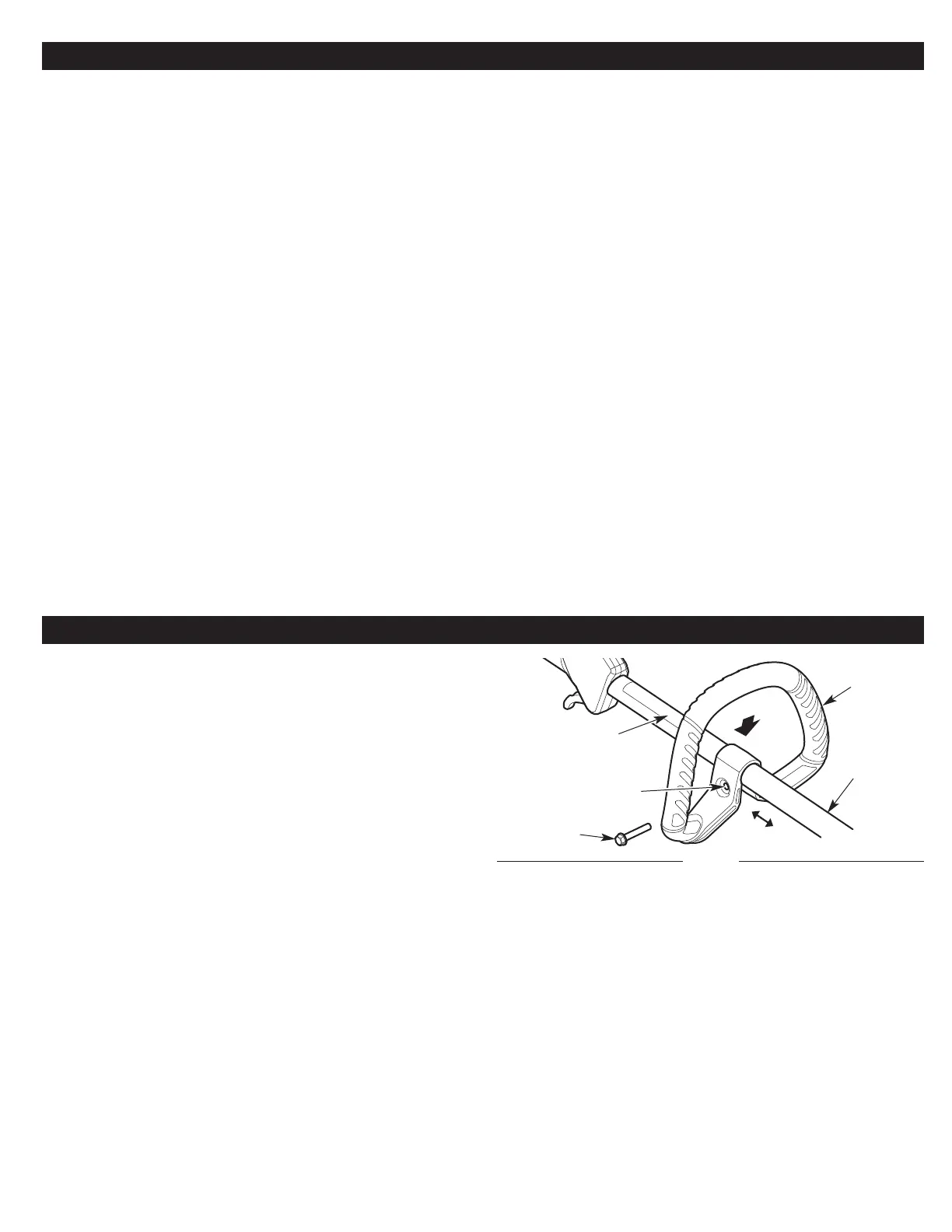
Installing the Handle
1. Push the handle down onto the shaft housing (Fig. 1). Make sure
the bolt hole faces to the right (Fig. 1).
2. Insert the bolt into the bolt hole and push it through (Fig. 1).
Tighten the bolt with a flat-head screwdriver, but do not tighten
the bolt completely .
3. Hold the unit in the operating position (Fig. 8) and move the
handle to a c
omfortable location (Fig. 1). Make sure
the handle is
positioned beyond the end of the safety label (Fig. 1).
4. Tighten the bolt with a flat-head screwdriver until the handle is
secure.
Adjusting the Handle
If the handle requires adjustment:
1. Loosen the bolt with a flat-head screwdriver (Fig. 1).
NOTE: If the handle was pre-installed under the shaft housing,
rotate the handle until it is in the proper upr
ight position (Fig. 1).
2
. Hold the unit in the operating position (Fig. 8) and move the
handle to a comfortable location (Fig. 1). Make sure the handle is
positioned beyond the end of the safety label (Fig. 1).
3. Tighten the bolt with a flat-head screwdriver until the handle is
secure.
Fig. 1
Bolt Hole
Handle
Shaft
Housing
Bolt
Safety Label
All specifications are based on the latest product information available at the time of printing. We reserve the right to make changes at any
time without notice.
*Use 0.080 in. (2.03 mm) diameter line for light-duty jobs and maximum runtime.
*Use 0.090 in. (2.29 mm) diameter line for heavy-duty jobs and a small compromise in runtime (available at www.troybilt.com).
 Loading...