Assembly
To preventpersonal injuryor property
damage, do not attempt to start the
engine until all assembly steps are
complete and you have read and
understand the safety, controls and
operatinginstructionsinthismanual.
INTRODUCTION
Pleasecarefullyfollow theseassembly
stepsto properly prepareyour machine
for use. We recommendthat you read
this Sectionin its entiretybeforebegin-
ningassembly.
NOTE:All referencesto left, right,front
and rearof the machineare determined
bystandingbehindthehandlebarsand
facingthe direction of forward travel.
INSPECTIONAFTERDELIVERY
Inspectthe shippingcrateand machine
immediatelyafterdelivery. Makesure
neitherthecarton northe contentshave
beendamaged.
If youfind or suspectanydamage,con-
tact thecarrier (trucking company)
immediately. Informthem of the specific
damageandthatyou wish to file a claim.
To protectyour rights, besureto put
this in writing to the carrier within 15
days. Thecarrierwill let you knowhow
to proceedwith your claim. Pleaselet us
knowif you needanyassistance.
TOOLS/MATERIALSNEEDED:
• WireCutter
• 7/16" Wrench
• 3/8" Wrench
• Two 1/2" Wrenches
• Scissorsor PenKnife
• Needle-nosePliers
• Motor Oil(seeStep 5)
• TireGauge
ASSEMBLYSTEPS
IMPORTANT:MOTOROIL MUSTBE
ADDEDTOTHEENGINEBEFOREIT IS
STARTED.FOLLOWINSTRUCTIONSIN
THIS"ASSEMBLY"SECTION.
STEP1: Unpacking Mower
NOTE:LEFTand RIGHTsides of the unit
areasviewedfrom the operator'sposi-
tion behindthehandlebars.
1. Cut metalstraps, if present,securing
unitto pallet.Leaveuniton pallet during
assembly(tosafelyremoveunitfrom
pallet,wait until you havecompletedas-
semblysteps 1-4).
2. Removeany protectivepackaging
from aroundthe handlebars.Cutthe
plastictie straps holdingthe four long
control rodsto the handlebars.Donot
removethe two long handlebarstruts
that areattachedto thetop of the
handlebars.
STEP2: Attach Handlebars
to Engine Deck
1. Removetheplastic ties holdingthe
wheeldrive rod (F,Figure2-7) to theleft
handlebarandthe bladedriverod (C,
Figure2-7) to the right handlebar.Put
the rodsaside.
NOTE:Fourscrews(D, Figure2-2) are
usedto connectthe handlebarsto the
enginedeck. At thefactory, these
screwsarethreadedinto lock nuts
weldedto the backsides ofthe deck.
2. Removeandsavethe four 5/16"-18
x 3/4"screws mentionedinthe NOTE
above.
3. Fromthe front of the unit,tilt the
right-sidehandlebarup overthe air
cleanercoverandlift the otherhandlebar
upward. Rotatethe handlebarsoverthe
engineandposition the handlebarends
(E,Figure2-2) againstthesidesof the
enginedeck.
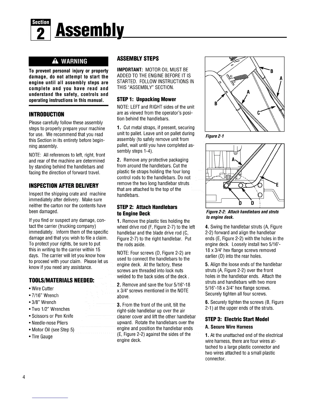
Figure2-1
E
_ r D D
i
Figure2-2: Attachhandlebarsandstruts
toenginedeck.
4. Swingthe handlebarstruts (A, Figure
2-2) forward andalign thehandlebar
ends(E, Figure2-2) with theholes in the
enginedeck. Looselyinstall two 5/16"-
18x 3/4"hexflange screwsremoved
earlier(D) intothe rearholes.
5. Align theloose ends of the handlebar
struts (A, Figure2-2) over thefront
holes in thehandlebarends. Attachthe
struts and handlebarswith two more
5/16"-18x 3/4" hexflangescrews.
Securelytightenall four screws.
6. Securelytightenthe screws(B, Figure
2-1) atthe upperendsof the struts.
STEP3: Electric Start Model
A. SecureWireHarness
1. Atthe unattachedendof theelectrical
wire harness,therearefour wiresat-
tachedto a largeplasticconnectorand
two wires attachedto a small plastic
connector.
 Loading...