Section2: Assembly
2. Plugthelargeconnectorinto the bot-
tom of theignition keyswitchthat islo-
catedonthe undersideof the handlebar
console(not pictured).
3. Usetwo cableties to securethewire
harnessto theright handlebarandaway
from any movingparts. Placethe ties an
equaldistanceapart.
B. AttachWireLeadsto Battery
1. Thebattery is locatedatthe rear,
right-side ofthe enginedeck.
2. At thelower end ofthe electrical
wiring harness,locatea redwire lead
anda blackwire lead.
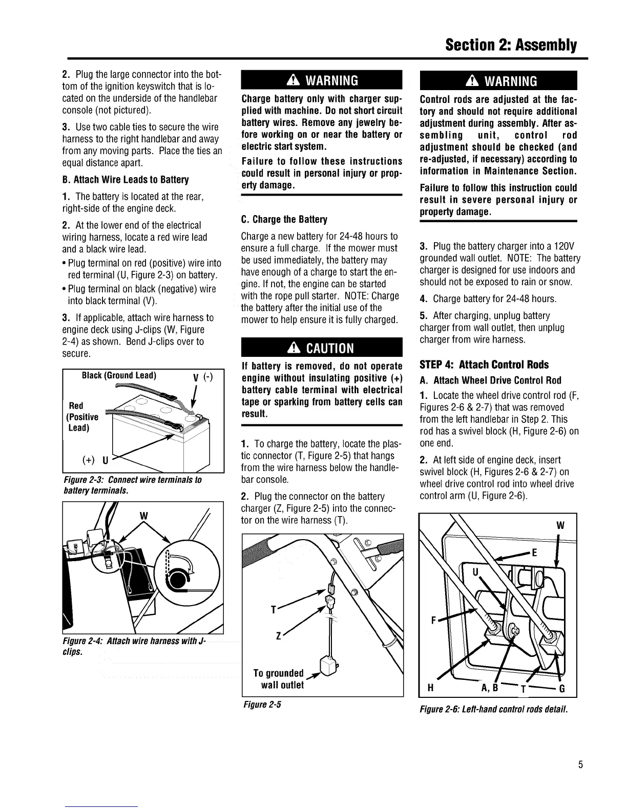
• Plugterminal on red(positive)wire into
redterminal (U, Figure2-3) on battery.
• Plugterminalon black(negative)wire
into blackterminal (V).
3. If applicable,attachwire harnessto
enginedeckusingJ-clips (W, Figure
2-4) asshown. BendJ-clips overto
secure.
Black(Ground Lead) V (-)
Red
(Positive
Lead)
(+) U
Figure2-3: Connectwireterminalsto
batteryterminals.
W
Figure2-4: AttachwireharnesswithJ-
clips.
Chargebatteryonly with chargersup-
pliedwith machine.Donotshortcircuit
batterywires. Removeany jewelrybe-
fore workingon or near the batteryor
electricstartsystem.
Failure to follow these instructions
couldresultin personalinjury or prop-
ertydamage.
C. Chargethe Battery
Chargea newbatteryfor 24-48 hours to
ensureafull charge. If the mowermust
be usedimmediately,the batterymay
haveenoughof a chargeto start the en-
gine.If not, the enginecanbestarted
with the ropepull starter. NOTE:Charge
the batteryafter theinitial use ofthe
mowerto helpensure it isfully charged.
If battery is removed, do not operate
enginewithout insulating positive (+)
battery cable terminal with electrical
tape or sparkingfrom batterycells can
result.
1. To chargethe battery,locatethe plas-
tic connector (T, Figure2-5) that hangs
from the wire harnessbelowthehandle-
barconsole.
2. Plugtheconnectoron the battery
charger(Z, Figure2-5) into the connec-
tor on thewire harness(T).
T
Z
To grounded
wall outlet
Figure2-5
Controlrodsare adjusted at the fac-
tory andshouldnot requireadditional
adjustmentduringassembly.Afteras-
sembling unit, control rod
adjustment should be checked (and
re-adjusted,ifnecessary)accordingto
informationin MaintenanceSection.
Failureto follow this instructioncould
result in severe personal injury or
propertydamage.
3. Plugthebatterychargerinto a 120V
groundedwall outlet. NOTE:The battery
chargeris designedfor use indoors and
should not beexposedto rainor snow.
4. Chargebatteryfor 24-48 hours.
5. After charging,unplug battery
chargerfrom wall outlet,then unplug
chargerfrom wire harness.
STEP4: Attach Control Rods
A. AttachWheelDriveControlRod
1. Locatethe wheeldrivecontrol rod (F,
Figures2-6 & 2-7) that wasremoved
from the left handlebarin Step2. This
rod hasa swivel block (H, Figure2-6) on
oneend.
2. At left side ofenginedeck,insert
swivel block(H, Figures2-6 & 2-7) on
wheeldrive control rod into wheeldrive
control arm (U, Figure2-6).
W
H A,B _G
Figure2-6:Left-handcontrolrodsdetail.
 Loading...