Section2: Assembly
BB
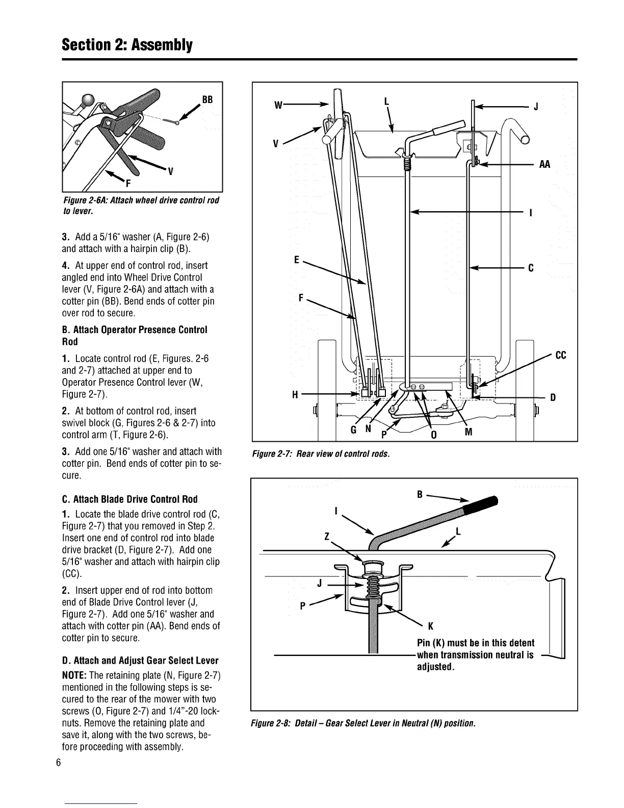
Figure2-6A:Attachwheeldrivecontrolrod
to lever.
3. Adda 5/16"washer(A,Figure2-6)
andattachwith a hairpinclip (B).
4. At upperend of control rod, insert
angledend intoWheel DriveControl
lever(V, Figure2-6A)andattach with a
cotterpin (BB).Bendendsof cotter pin
overrod to secure.
B. AttachOperatorPresenceControl
Rod
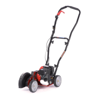
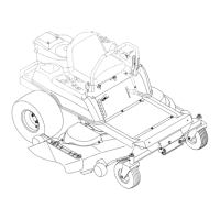
1. Locatecontrol rod (E,Figures.2-6
and2-7) attachedat upperendto
OperatorPresenceControllever(W,
Figure2-7).
2. At bottom ofcontrol rod,insert
swivelblock (G, Figures2-6 & 2-7) into
control arm (T, Figure2-6).
3. Addone5/16"washerandattachwith
cotterpin. Bendendsof cotter pinto se-
cure.
C. AttachBladeDriveControlRod
1. Locatethe bladedrive control rod (C,
Figure2-7) that you removedin Step 2.
Insertoneend of control rod into blade
drivebracket(D, Figure2-7). Add one
5/16"washerandattachwith hairpin clip
(cc).
2. Insert upperend of rod into bottom
endof BladeDriveControllever(J,
Figure2-7). Add one5/16"washerand
attachwith cotter pin (AA). Bendends of
cotterpin to secure.
D. AttachandAdjustGearSelectLever
NOTE:Theretainingplate (N, Figure2-7)
mentionedinthe following steps isse-
curedto the rearofthe mowerwith two
screws(0, Figure2-7) and 1/4"-20 lock-
nuts. Removethe retainingplate and
saveit, alongwith the two screws,be-
foreproceedingwith assembly.
6
V
F
G N
Figure2-7: Rearviewofcontrolrods.
0
M
C
f
2
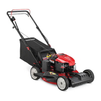
Figure2-8: Detail - GearSelectLeverin Neutral(N) position.
K
Pin(K)mustbe inthisdetent
whentransmissionneutralis --_
adjusted.