Section2: Assembly
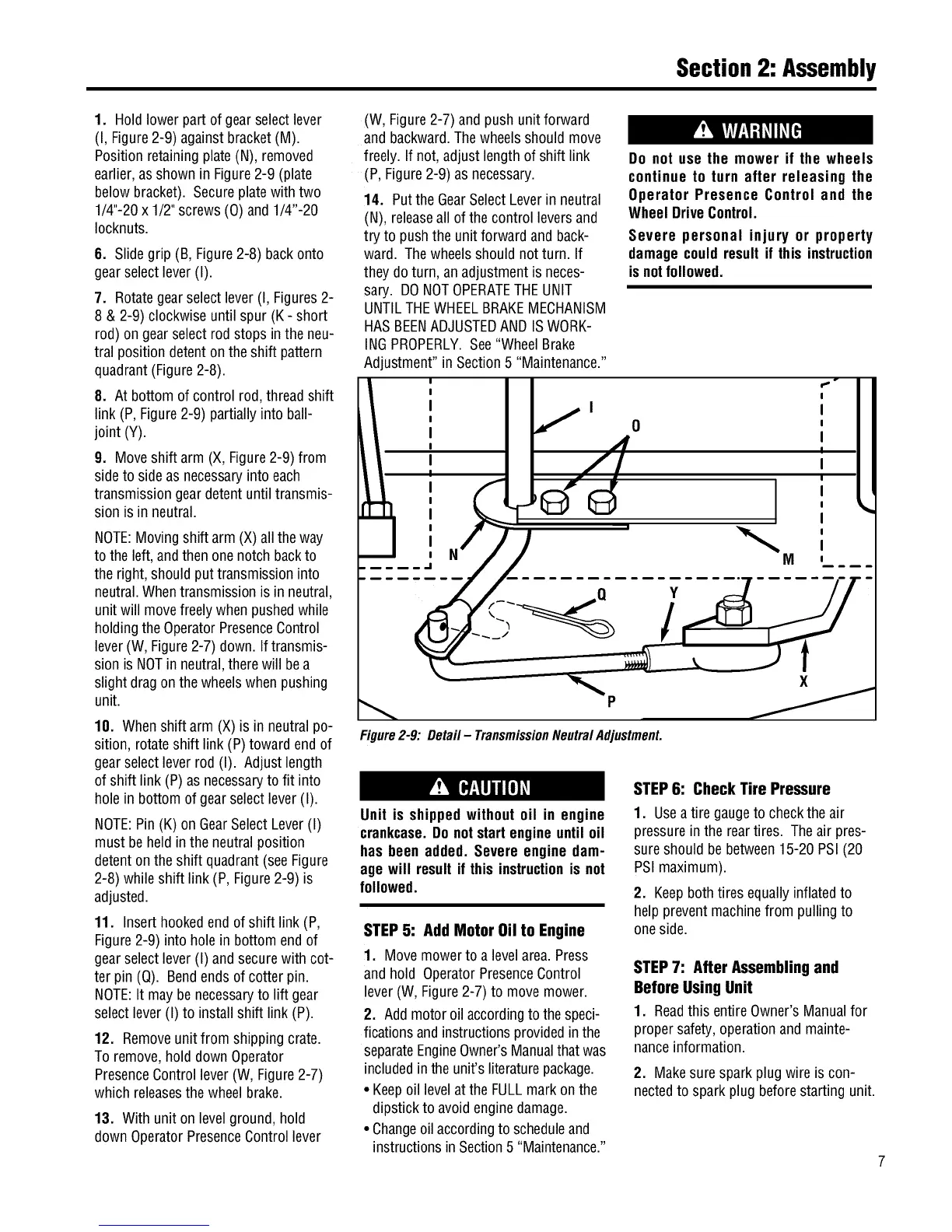
1. Hold lowerpart of gearselect lever
(I, Figure2-9) againstbracket(M).
Position retainingplate(N), removed
earlier,asshown in Figure2-9 (plate
belowbracket). Secureplatewith two
1/4"-20x 1/2"screws (0) and 1/4"-20
Iocknuts.
6. Slidegrip (B, Figure2-8) backonto
gearselectlever(I).
7. Rotategearselect lever(I, Figures2-
8 & 2-9) clockwise until spur (K - short
rod) ongearselectrod stops in the neu-
tral position detenton theshift pattern
quadrant(Figure2-8).
8. At bottom ofcontrol rod,threadshift
link (P,Figure2-9) partially into ball-
joint (Y).
9. Moveshift arm (X,Figure2-9) from
sideto sideas necessaryinto each
transmissiongeardetent until transmis-
sion isin neutral.
NOTE:Movingshift arm(X) alltheway
tothe left, andthen onenotch backto
theright, should put transmissioninto
neutral.Whentransmissionis in neutral,
unitwill movefreelywhenpushedwhile
holdingtheOperatorPresenceControl
lever(W, Figure2-7) down. Iftransmis-
sionis NOTin neutral,therewill bea
slight dragon the wheelswhenpushing
unit.
10. Whenshift arm (X)is in neutral po-
sition, rotateshift link (P)toward end of
gearselectleverrod (I). Adjustlength
of shift link (P) asnecessaryto fit into
hole in bottom of gearselectlever (I).
NOTE:Pin (K) on GearSelectLever(I)
must beheld inthe neutralposition
detentonthe shift quadrant(see Figure
2-8) whileshift link (P, Figure2-9) is
adjusted.
11. Insert hookedendof shift link (P,
Figure2-9) into holein bottom end of
gearselectlever(I) andsecurewith cot-
ter pin (Q). Bendendsof cotter pin.
NOTE:It may benecessaryto lift gear
selectlever(I) to install shift link (P).
12. Removeunit from shipping crate.
Toremove,hold down Operator
PresenceControllever(W, Figure2-7)
which releasesthewheel brake.
13. With unit on levelground,hold
downOperatorPresenceControllever
(W, Figure2-7) andpush unitforward
and backward.Thewheelsshouldmove
freely. If not, adjustlengthof shift link
(P,Figure2-9) as necessary.
14. Putthe GearSelectLeverin neutral
(N), releaseall ofthe control leversand
try to push theunit forwardand back-
ward. Thewheelsshouldnot turn. If
they do turn, an adjustmentis neces-
sary. DONOTOPERATETHEUNIT
UNTILTHEWHEELBRAKEMECHANISM
HASBEENADJUSTEDANDISWORK-
INGPROPERLY.See"WheelBrake
Adjustment" in Section5 "Maintenance."
Do not use the mower if the wheels
continue to turn after releasing the
Operator Presence Control and the
WheelDriveControl.
Severe personal injury or property
damagecouldresult if this instruction
isnotfollowed.
: ;° I
I .,I I I
I I
I / o I I
o4
,
I I
I I
J.
Figure2-9: Detail- TransmissionNeutralAdjustment.
Unit is shippedwithout oil in engine
crankcase.Do notstartengineuntil oil
has been added. Severe engine dam-
age will resultit this instructionis not
followed.
STEP5: Add Motor Oil to Engine
1. Movemowerto a levelarea.Press
and hold OperatorPresenceControl
lever(W,Figure2-7) to movemower.
2. Add motoroil accordingto the speci-
ficationsandinstructionsprovidedin the
separateEngineOwner'sManualthat was
includedin theunit's literaturepackage.
• Keepoil levelat the FULLmarkon the
dipstick to avoidenginedamage.
• Changeoil accordingto scheduleand
instructionsin Section5 "Maintenance."
STEP6: Check Tire Pressure
1. Useatire gaugeto checkthe air
pressurein the reartires. Theair pres-
sureshould bebetween15-20 PSI(20
PSImaximum).
2. Keepbothtires equally inflatedto
help preventmachinefrom pulling to
oneside.
STEP7: After Assembling and
Before Using Unit
1. Readthis entireOwner'sManualfor
propersafety,operationand mainte-
nanceinformation.
2. Makesurespark plug wire is con-
nectedto spark plug beforestarting unit.
 Loading...