the control levers.
7. Automotive-type tire pressure gauge.
8. Ruler.
9. Sturdy wood box or block 2-1/2"
-3
-1/2" high
(Junior Model only).
•
You
may
subs
t
itu
te adj
ustab
le
wrenche
s.
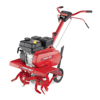
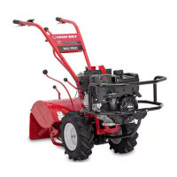
Compare the parts that you received to Photos 2-1 and 2-2. If you are missing any items, please call
us at one of the telephone numbers listed on page 3 of this Manual.
If you notice any freight damage, either at the time of delivery or later during assembly, contact the
freight terminal and tell them you will be filing a written claim (do so within 15 days). The terminal will
advise you as to how to proceed. However, if you meet any problems with this procedure, please call
us so we can provide assistance.
Before you attempt to move the tiller off the shipping carton, please install the handlebars (Step 2).
With the handlebars installed, you'll have better leverage and be more easily able to move the tiller to a
level area so you can continue the assembly.
You'll need the following tools to assemble your tiller:
1. Two 9/16" wrenches.
*
2. One medium-size flat blade screwdriver.
3. One open end 3/8" wrench.*
4. Scissors (to trim the plastic ties).
5. One 7/16" wrench (electric models only).*
6. A piece of wood to tap the knobs securely on
NOTE
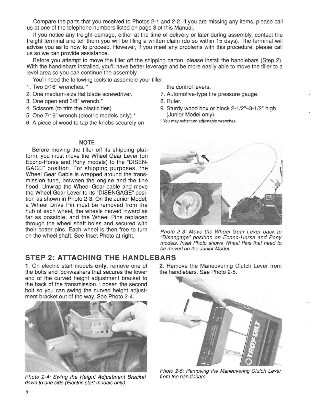
Before moving the tiller off its shipping plat-
form, you must move the Wheel Gear Lever (on
Econo-Horse and Pony models) to the "DISEN-
G
AGE
"
position
. For shippin g purposes, the
Wheel Gear Cable is wrapped around the trans-
mission tube, between the engine and the tine
hood. Unwrap the Wheel Gear cable and move
the Wheel Gear Lever to its "DISENGAGE" posi-
tion as shown in Photo 2-3. On the Junior Model,
a Wheel Drive Pin must be removed from the
hub of each wheel, the wheels moved inward as
far as possible, and the Wheel Pins replaced
through the wheel shaft holes and secured with
their cotter pins. Each wheel is then free to turn
on the wheel shaft. See Inset Photo at right.
Photo 2-3: Move the Wheel
Gear
Lever
back
to
"Disengage"
posit
ion on Econo-Horse
and
Pony
models. Inset Photo shows Wheel Pins that need to
be moved on the Junior Model.
STEP 2: ATTACHING TH E HANDLEBARS
1. On electric start models only, remove one of
the bolts and lockwashers that secures the lower
end of the curved height adjustment bracket to
the back of the transmission. Loosen the second
bolt so you can swing the curved height adjust-
ment bracket out of the way. See Photo 2-4.
~
Photo 2-4: SWing the Height
Ad
justm
ent
Bracket
down to one side (Electric start models only).
8
2. Remove the Maneuvering Clutch Lever from
the handlebars. See Photo 2-5.
Photo 2-5: Removing the Maneuvering Clutch Lever
from the handlebars.