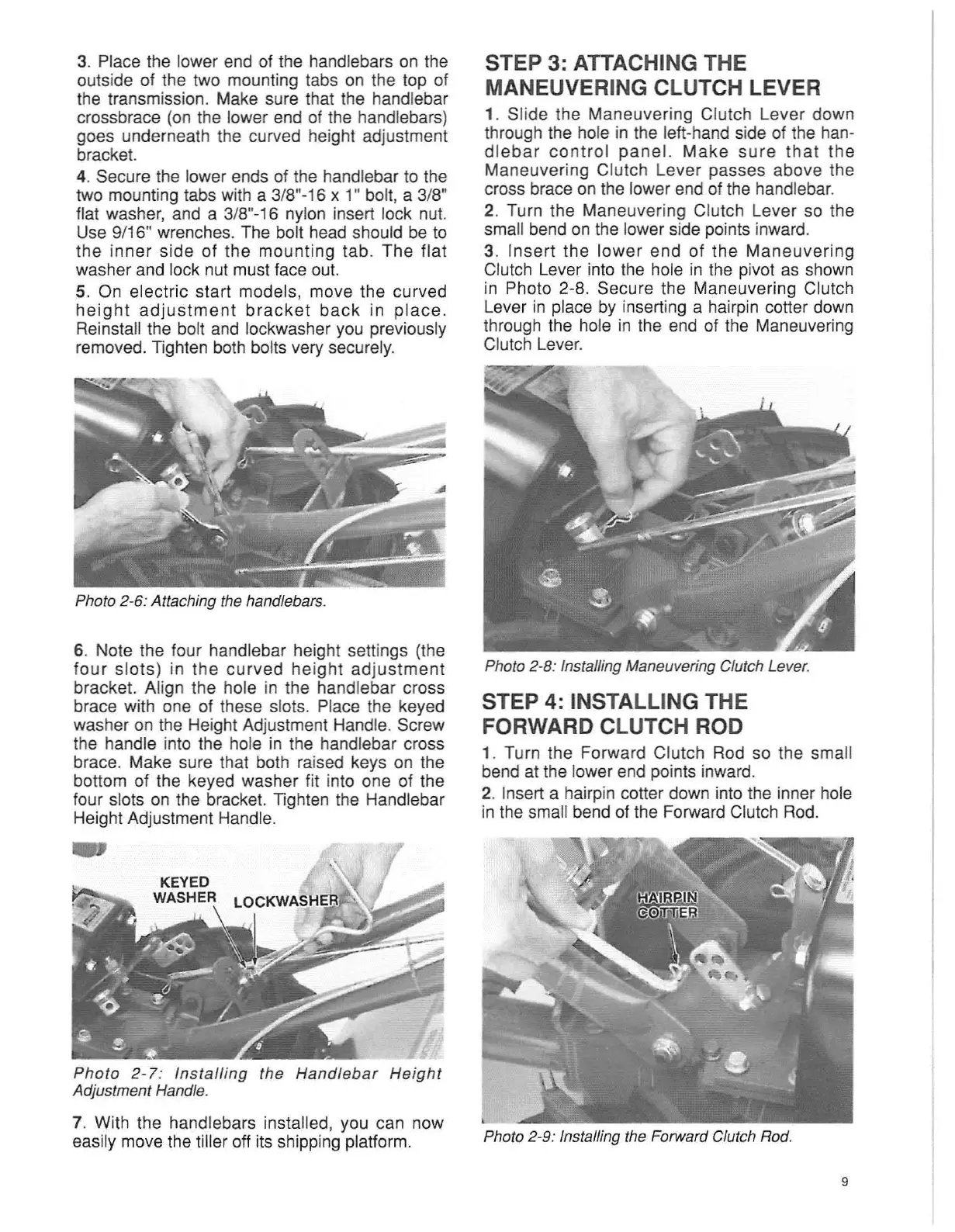
3. Place the lower end of the handlebars on the
outside of the two mounting tabs on the top of
the transmission. Make sure that the handlebar
crossbrace (on the lower end of the handlebars)
goes underneath the curved height adjustment
bracket.
4. Secure the lower ends of the handlebar to the
two mounting tabs with a 3/8"-16 x 1" bolt, a 3/8"
flat washer, and a 3/8"-16 nylon insert lock nut.
Use 9/16" wrenches. The bolt head should be to
the inner side of the mounting tab .
The
flat
washer and lock nut must face out.
5. On electric start models, move the curved
heig
ht adjustment
brac
ket
back
in pl ace.
Reinstall the bolt and lockwasher you previously
removed. Tighten both bolts very securely.
Photo 2-6: Attaching the handlebars.
6. Note the four handlebar height settings (the
four
slots) in
the
curved
height ad
justment
bracket. Align the hole in the handlebar cross
brace with one of these slots. Place the keyed
washer on the Height Adjustment Handle. Screw
the handle into the hole in the handlebar cross
brace. Make sure that both raised keys on the
bottom of the keyed washer fit into one of the
four slots on the bracket. Tighten the Handlebar
Height Adjustment Handle.
Phot
o
2-7
: In sta
ll
ing the Ha
ndleba
r
Height
Adjustment Handle.
7. With the handlebars installed , you can now
easily move the tiller off its shipping platform.
STEP 3: ATTACHING THE
MANEUVERING CLUTCH LEVER
1. Slide the Maneuvering Clutch Lever down
through the hole in the left-hand side of the han-
dlebar
control
panel
.
Make
sure
that
the
Maneuvering Clutch Lever passes above the
cross brace on the lower end of the handlebar.
2. Turn the Maneuvering Clutch Lever so the
small bend on the lower side points inward.
3. I
nsert
the lower end of the
Maneuvering
Clutch Lever into the hole in the pivot as shown
in Photo 2-8. Secure the Maneuvering Clutch
Lever in place by inserting a hairpin cotter down
through the hole in the end of the Maneuvering
Clutch Lever.
Photo 2-8: Installing Maneuvering Clutch Lever.
STEP 4: INSTALLING THE
FORWARD CLUTCH ROD
1. Turn the Forward Clutch Rod so the small
bend at the lower end points inward.
2. Insert a hairpin cotter down into the inner hole
in the small bend of the Forward Clutch Rod.
Photo 2-9: Installing the Forward Clutch Rod.
9