Troy-Bilt Small Frame Tillers
25
8.31. If the drive shaft assembly end play is not within
tolerance, .005” to .015”, perform the above pro-
cedures again.
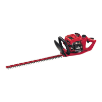
8.32. If the drive shaft assembly is within .005” to
.015”, continue through this section. See Figure
8.32.
8.33. Remove the drive shaft assembly and all compo-
nents. See Figure 8.33.
Figure 8.32
Drive Shaft Assembly
End Play Tolerance - .005” to .015”
Figure 8.33
All Drive Shaft Assembly Components Removed
Rear Bearing Cap
Short Hex Screw
Rear Bearing Cap Shims
Rear Tapered Roller Bearing Race
Drive Shaft Assembly
Hex Flange Screws
Support Washer
Front Tapered Roller Bearing
Race
Snap Ring
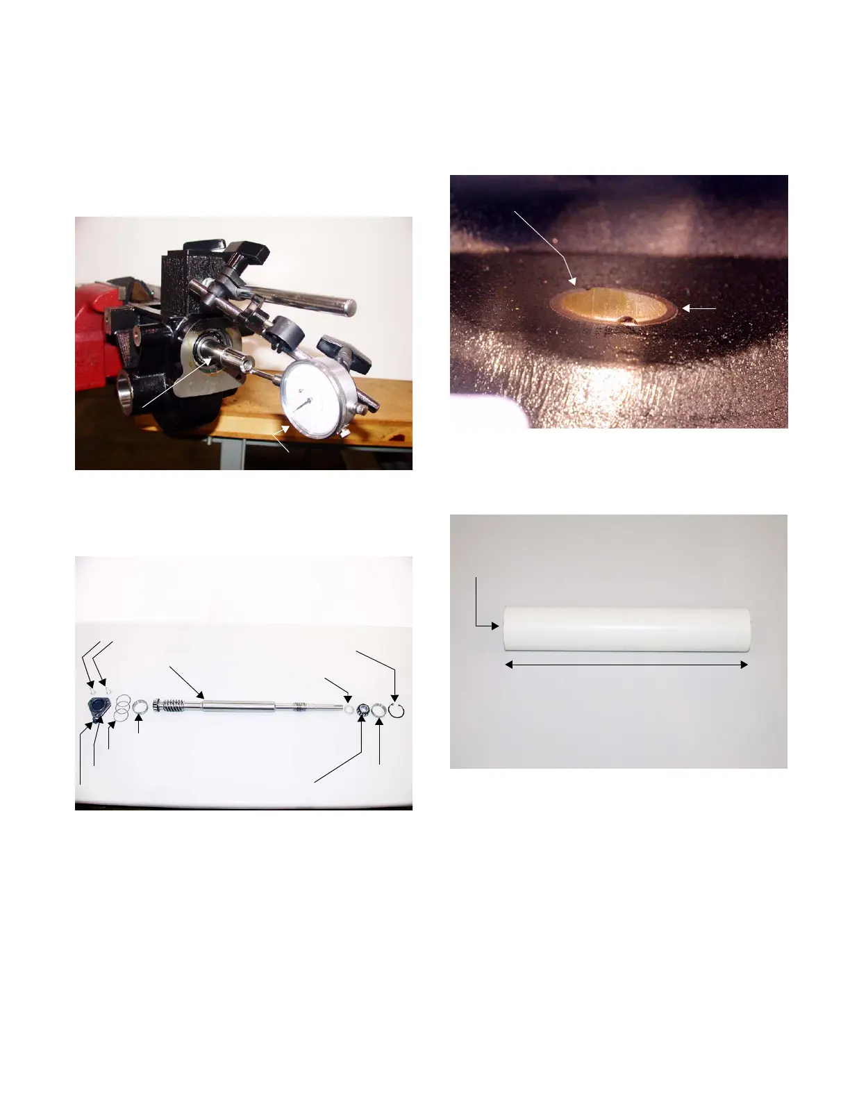
8.34. Drive one of the wheel shaft’s bronze bushings
into the transmission housing until it is flush with
the inside of the housing using a bushing driver
and hammer. See Figure 8.34.
NOTE: A 1” I.D. PVC pipe by 7” long works well
as a bushing installation tool. See Image Below.
Figure 8.34
Bronze Bushing
Flush
1” ID PVC Pipe
7” Long
1” ID PVC Pipe for Bushing Installation
 Loading...