IMPORTANT: READ THE OPERATOR’S MANUAL THOROUGHLY AND FOLLOW THE SAFE OPERATION PRACTICES WHILE OPERATING THE UNIT.
R
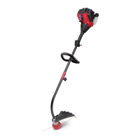
emoving Unit From Carton
P
lace shield onto mount
bracket. Securely screw 2 shield
screws through holes on mount
b
racket and into shield. Make
sure screws are tightened equally
s
o there is an equal gap between
bracket and shield on each side.
A
ssemble The Unit
11 2
Remove all contents from
t
he carton.
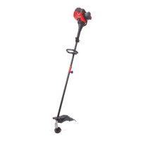
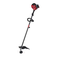
Starter Rope
Fuel Cap
Throttle Control
On/ Off Switch
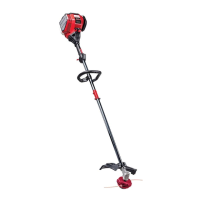
D-Handle
Ez-Link™
Cutting Head Shield
Need Help?
Call 1-800-828-5500
Electric Starter or
Power Start Bit Optional!
THESE OPTIONAL ACCESSORIES
A
RE SOLD SEPARATELY!
This unit has an alternate starting method
that many find easier to use than pulling a
rope. Please contact a local retailer or call
1-800-828-5500 for more information.
I
nformation may also be found at
www.troybilt.com
DIDN’T START?
Repeat these instructions.
I
F engine fails to start after 2 attempts,
move choke lever to position 3 and pull
the starter rope until engine starts
IF unit still fails to start, refer to the
operator’s manual for additional starting
a
nd troubleshooting information
N
o Tools Required!
Assemble The Unit
S
tarting The Unit
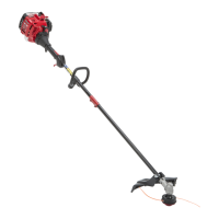
R
emove cap from lower
boom. Push cutting
attachment into coupler.
T
urn coupler knob clockwise
to tighten.
Mix thoroughly in separate
f
uel can:
– 3.2 fl. oz. of 2-cycle
e
ngine oil
– 1 gallon of unleaded
g
asoline
NOTE: Do not mix directly in
fuel tank.
Place unit on a level surface.
Fill fuel tank.
Press primer bulb 10 times,
or until fuel is visible
C
rouch in starting position. SQUEEZE and HOLD
throttle for ALL further
steps.
P
ull rope 5 times.
M
ove choke lever to
Position 2 and squeeze
throttle.
P
ull rope 3-5 times to start
engine. Run unit for 30-60
seconds to warm up.
C
ontinue to squeeze
throttle. Move choke lever
to Position 3.
11 2
R
emove all contents from
carton.
5 6 7
19 10
3
P
ut D-handle on shaft. Move
handle a minimum 6 inches
away from shaft grip. Insert
c
lamp bolt and tighten the
wing nut.
Move choke lever to
Position 1.
C
ontinue to squeeze
throttle. Run unit for an
additional 60 seconds to
complete warm-up. Unit
may be used during this
time.
8
4
Starting The Unit
11
12
13
14
1
5
Primer
Bulb
10 X
5 X
3-5 X
Choke Lever
1
Gallon 3.2 oz
4
0:1
Choke Lever
Choke Lever
Min. 6"
Bump
Knob
Inner
Reel
Outer
Spool
Spring
Top Hole
Bottom Hole
Split Wall
Unscrew the bump knob
counterclockwise.
Remove the inner reel and
spring.
Cut one 6-foot (1.8 m) length
of new 0.095” split line
trimming line. Split each end
about 6 inches (150 mm).
Insert the end of one line into
the top hole and the end of
the other line into the bottom
hole.
Wind the line tightly in the
direction shown on the inner
reel. The split wall will divide
the line. Wind the line until it
is completely divided and
about 6 inches (150 mm) of
line remains.
Insert the two 6-inch sections
into the two .095 holding
slots.
11 2
Pass the two line ends
through the eyelets. Place the
spring inside the inner reel.
Insert the inner reel into the
outer spool. Push the inner
reel and outer spool together.
Reloading the Line*
3
4
5
6
7
Hold the inner reel and outer
spool together. Firmly pull the
two line ends to release them
from the holding slots. Screw
the bump knob on clockwise.
Tighten the bump knob
securely.
18
For replacement line, call 1–800-800-7310 or go to
an authorized service dealer.
For single line installation or replacement spool
installation instructions, refer to the Replacing the
Trimming Line section of this manual.
*This is to assist in the reloading of Splitline® only. These instructions
are NOT part of the fast assembly instructions. Line does not need to
be installed on the initial assembly and start-up.
Reloading the Line
Holding Slots
Eyelets