2
Combi 2 E / 4 E CP plus (Australia)
Table of contents
Symbols used ........................................................................ 3
Function description ......................................................... 3
Safety instructions ............................................................ 4
Important operating notes ............................................... 5
Operating instructions
Digital control panel .............................................................. 5
Room temperature sensor .................................................... 5
Safety/drain valve .................................................................. 5
Filling the hot water system .................................................. 6
Draining the hot water system .............................................. 6
Electrical operation 230 / 240 V – option – .................. 6
Start-up ................................................................................ 6
Switching off ...................................................................... 6
Maintenance ....................................................................... 6
Fuses .................................................................................... 7
Fuse 12 V ............................................................................... 7
Fuse 240V ............................................................................. 7
Overheating protection 240 V ............................................... 7
Faults .................................................................................... 7
Troubleshooting guide (water supply) ................................... 7
Accessories ......................................................................... 8
Technical data ..................................................................... 8
Truma warranty policy ..................................................... 9
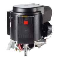
1 Control panel (digital)
2 Room temperature sensor
3 Cold water connection
4 Hot water connection
5 Gas connection (with pressure test point – not shown)
6 Hot air outlets
7 Recirculated air intake
8 Waste gas discharge
9 Combustion air infeed
10 Electronic control unit
11 Water container (10 litres)
12 Burner
13 Heat exchanger
14 Power electronics
15 Heating elements 240 V
16 Overheating switch 240 V
17 Safety/drain valve
18 Water pressure reducer
17
2
3
5
7
8
9
10
10
14
15
16
4
12
13
6
6
18
1
Fig. 1