3
18 Water pressure reducer
Table of contents
Symbols used ........................................................................ 3
Function description ......................................................... 3 Safety
instructions ............................................................ 4
Important operating notes ............................................... 4
Operating instructions
Digital Control Panel ............................................................. 5 Room
temperature sensor .................................................... 5 Safety/drain
valve .................................................................. 5 Filling the boiler
..................................................................... 5 Draining the boiler
................................................................. 5
Start-up ................................................................................ 6
Switching off ...................................................................... 6
Maintenance ....................................................................... 6 Fuses
.................................................................................... 6 Fuse 12 V
............................................................................... 6 Fuse 240 V
............................................................................. 6 Overheating
protection 240 V ............................................... 6 Faults
.................................................................................... 7
Troubleshooting guide (water supply) ................................... 7
Technical data ..................................................................... 7
Accessories ......................................................................... 8
Truma warranty policy ..................................................... 8
Installation instructions
Intended use .......................................................................... 9
Approval ................................................................................ 9
Regulations ........................................................................... 9
Selecting a location ........................................................... 9
Securing the device ......................................................... 10 Exhaust
gas removal ....................................................... 10 Installing the
wall cowl ........................................................ 10 Connecting the
exhaust double duct to the device ............ 11 Recirculated air intake
.................................................... 11 Warm air distribution
...................................................... 11
Gas connection ................................................................. 12
Water connection ............................................................ 12
Mounting the safety/drain valve ......................................... 13
Installation of the pressure reducer .................................... 13 Water
pipe routing .............................................................. 13 Installing
the room temperature sensor ...................... 13 Installing the
control panel ............................................ 14
Electrical connections ..................................................... 14 12 V
voltage supply ............................................................. 14 Room
temperature sensor .................................................. 14 Control
panel / air conditioning system .............................. 14 240 V voltage
supply ........................................................... 15
Function test ..................................................................... 15
Warnings ........................................................................... 15
Symbols used
The unit must only be installed and repaired by an expert.
Symbol indicates a possible hazard.
Comment including information and tips.
Observe the ESD-regulations! An electro-static charge can
destroy the electronics. Ensure potential equalisation
before touching the electronics.
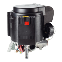
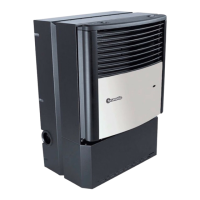
Function description
The Combi 2 E / 4 E CP plus (Australia) liquid gas heater is a warm-air
heater with integrated hot water boiler (10 litre capacity). The burner
is fan-assisted, which ensures that operation is problem-free, even
when on the move. The unit also has heating elements for electrical
operation.
In heating and hot water mode the heater can be used to heat the
room and heat water up at the same time. If only hot water is
required, select hot water mode.
3 different options are available for operating the unit:
– gas mode only
LPG for autonomous use
– electrical mode only
240 V for stationary use on camp sites
– or gas and electrical mode – mixed mode
Only possible in heating and hot water mode.
Heating and hot water mode
In heating and hot water mode, the unit automatically selects the
required operating level according to the temperature difference
between the temperature set on the control panel and the current
room temperature. If the boiler has been filled, the water is
automatically heated as well. The water temperature depends on the
selected operating mode and the heater output.
All 3 energy selection options can be used for winter deployment.
– In gas mode the unit automatically selects the operating level
that is required.
– In electrical mode output of 980 W (4.1 A) or 1960 W (8.1 A)
can be manually preselected in accordance with the fuse
protection at the camp site.
If more output is required (e.g. heating up or low outside
temperatures) gas or mixed mode should be selected so that
enough heating power is always available.
– In mixed mode 240 V electrical mode is preferred if the
power requirement is low (e.g. for maintaining the room
temperature). The gas burner is not enabled until the power
requirement is higher, and is the first to switch off during heat-up
operations.
Hot water mode
(with filled boiler only)
Gas mode or 240 V electrical mode is used to generate hot water.
The water temperature can be set to 60 °C.
– In gas mode the water is heated at the lowest burner setting.
Once the water temperature has been reached, the burner
switches off.
– In electrical mode output of 980 W (4.1 A) or 1960 W (8.1 A)
can be manually selected in accordance with the fuse protection at
the camp site.
Mixed mode is not possible. With this setting the unit
automatically selects electrical mode. The gas burner is not
enabled.
Safety instructions
The use of upright gas cylinders from which gas is taken in the gas
phase is mandatory for the operation of gas regulators, gas
equipment and gas systems. Gas cylinders from which gas is taken in
the liquid phase (e. g. for fork lifts) must not be used, since they
would result in damage to the gas system.