13
The boiler is now drained directly to the outside via the drain
valve. Place a bucket beneath the outlet to check whether the
water content has completely drained away (10 litres). There
shall be no claims under guarantee for damage caused
by frost!
Maintenance
Only original Truma parts may be used for maintenance and
repair work!
Biofilm, deposits and limescale must be removed using
chemicals to protect the unit from infestation by microorgan-
isms. Only chloride-free products must be used in order to
prevent damage to the unit.
The effectiveness of the use of chemicals to combat microor-
ganisms in the unit can be increased by heating the water in
the boiler to 70 °C at regular intervals.
Move the rotary switch on the control panel to position (c –
summer operation) 60 °C. The green (b) and yellow (g) LEDs
light up.
Once the water in the boiler has reached a temperature
of 60 °C, the burner will switch off and the yellow LED (g)
will go out. The unit must stay switched on for at least 30 min-
utes and no warm water may be removed. The residual heat in
the heat exchanger will heat the water up to 70 °C.
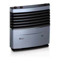
Fuses
The unit’s fuse is located on the electronics under the connec-
tion cover. Replace the unit’s fuse only with an identical fuse.
Device fuse: 10 A – slow – (T 10 A)
T 10 A
Disposal
The device must be disposed of in line with the administrative
regulations of the respective country in which it is used.
National regulations and laws (in Germany, for example, the
End-of-life Vehicle Regulation) must be observed.
In other countries, the relevant regulations must be observed.
Technical data
determined in accordance with EN 624
or Truma test conditions
Device category
I
3 B/P
in accordance with EN 437
Type of gas
Liquid gas (propane / butane)
Operating pressure
30 mbar (see type plate)
Water contents
10 litres
Heating up time from approx. 15 °C to approx. 60 °C
Boiler approx. 20 minutes (measured according to EN 15033)
Heater + boiler approx. 80 min.
Water pressure
max. 2.8 bar
Rated thermal output (automatic output levels)
Combi 4: 2000 / 4000 W
Combi 6: 2000 / 4000 / 6000 W
Gas consumption
Combi 4: 160 – 320 g/h
Combi 6: 160 – 480 g/h
Readiness-heat power requirement Combi 4 / Combi 6: 5.2 g/h
Air delivery volume (free-blowing without hot-air pipe)
Combi 4: with 3 hot-air outlets max. 249 m³/h
with 4 hot-air outlets max. 287 m³/h
Combi 6: with 4 hot-air outlets max. 287 m³/h
Current input at 12 V
Heater + boiler
Combi 4: Short-term max. 5.6 A
(average power consumption 1.1 A)
Combi 6: Short-term max. 5.6 A
(average power consumption 1.3 A)
Heating up of boiler: 0.4 A
Stand-by: 0.001 A
Heating element FrostControl (optional): maximum 0.4 A
Weight (without water contents)
Heater unit: 14.0 kg
Heater unit with peripheral devices: 14.5 kg
Declaration of conformity
The Truma Combi has been tested by the DVGW and complies
with the gas equipment directive (90/396/EEC) and the other
applicable EC directives. The following CE Product Ident. No.
is available for EU countries
Combi 4 / Combi 6: CE-0085BS0085
The heater complies with heater directive 2001/56/EC and
supplements 2004/78/EC and 2006/119/EC and bears the
type approval number
Combi 4: e1 00 0193
Combi 6: e1 00 0194
The device satisfies the EMC Directive 2004/108/EC.
The heater complies with the interference suppression
directive 2004/104/EC for vehicle engines with annexes
2005/83/EC and 2006/28/EC and bears type approval number:
e1 03 5020
The heating system satisfies the End-of-Life Vehicle Directive
(2000/53/EC) and the Drinking Water Directive 98/83/EEC.
The right to effect technical modifications is reserved!
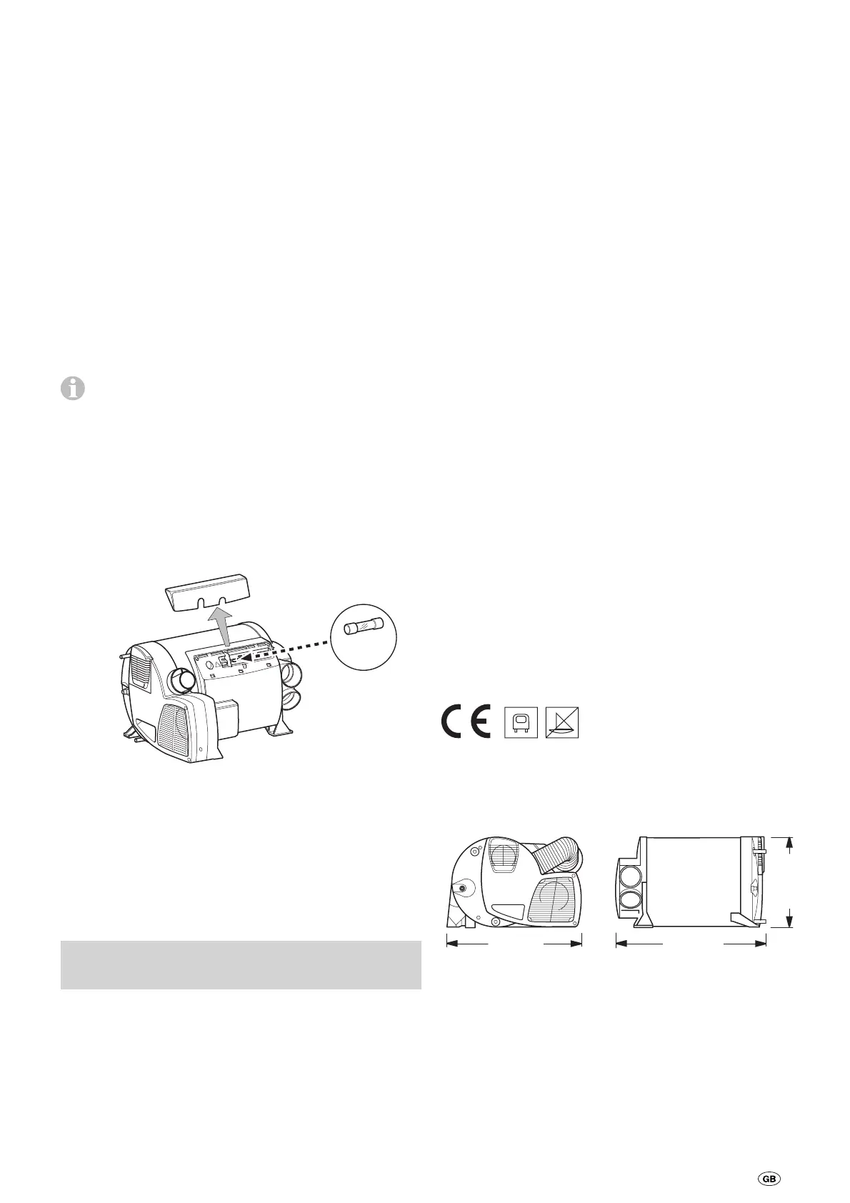
Dimensions
450 mm
510 mm
300 mm