30
34020-01190 - 01 - 03/2022
Installation Combi D
EN
•
The heater may not be installed on sloping surfaces
or vertically on the wall.
•
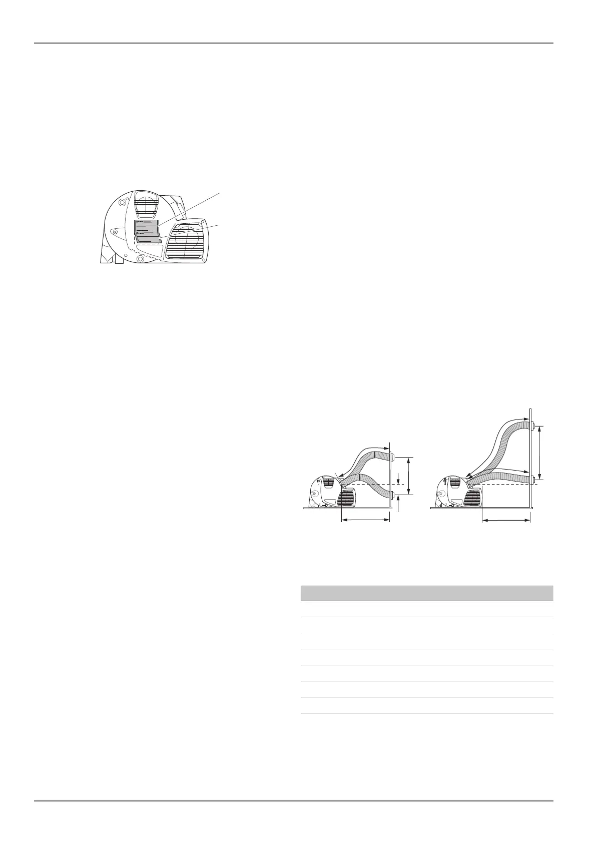
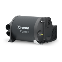
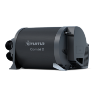
The scope of delivery includes a second type plate
(Fig. 9-2) (duplicate) with removable bar code.
If the type plate on the heater (Fig. 9-1) is not visible
after the heater has been installed, the second type
plate (duplicate) must be affixed to the appliance in
a clearly visible location.
The duplicate must only be used in conjunction with
the original.
1
2
Fig. 9
•
In order to heat the vehicle evenly throughout, the
heater must be installed in a location in the vehicle
that is as central as possible (in a wardrobe, stow-
age compartment or the like) so that the air distribu-
tion ducts can be routed with approximately equal
lengths. The installation space must have sufficient
openings for air intake – see “Circulated air intake”
and “Warm air distribution”.
•
The maximum lengths of the fuel lines (see fuel
connection) and the exhaust gas and air intake muf-
fler (see “Installing the exhaust system”) must be
observed.
2.4 Installing the exhaust system
CAUTION
Cuts caused by sharp edges on the exhaust
duct or insulating duct
Wear protective gloves
WARNING
Risk of fire, risk of suocation
Risk of fire from overheating and/or risk of suo-
cation from exhaust fumes if installed incorrect-
ly or if parts other than original Truma parts are
used for the exhaust gas system.
Use only original Truma parts for the exhaust
gas system.
Observe the installation instructions for the
exhaust gas system.
2.4.1 Dimensioning of the exhaust ducts
The duct kits must be ordered separately.
Installation only with the Combi D duct kits listed
below:
•
34502-01 Combi D duct kit, 0.6 m
•
34502-02 Combi D duct kit, 0.7 m
•
34502-03 Combi D duct kit, 1.0 m
•
34502-04 Combi D duct kit, 1.5 m
Do not crush or kink ducts during installation.
NOTICE
Damage to heat-sensitive components
caused by hot exhaust gases
Ensure a minimum 10mm gap between
the exhaust gas system and heat-sensitive
components.
Permissible duct lengths
Ducts with a length of at least 60 cm to a maximum of
100 cm can be routed with any amount of rising for the
wall cowl, or with a maximum fall of 20 cm.
Duct lengths from 100 cm to max. 150 cm may only be
installed rising.
When installing ducts, avoid any hanging sections
where water could accumulate.
d
b
c
a
g
e
f
d
Fig. 10
Measurement Value
a 60 – 100cm
b any
c max. 20cm
d max. 100cm
e 100 – 150cm
f 100cm
g any


 To Next Page