34020-01190 - 01 - 03/2022
Combi D Installation
31EN
1
2
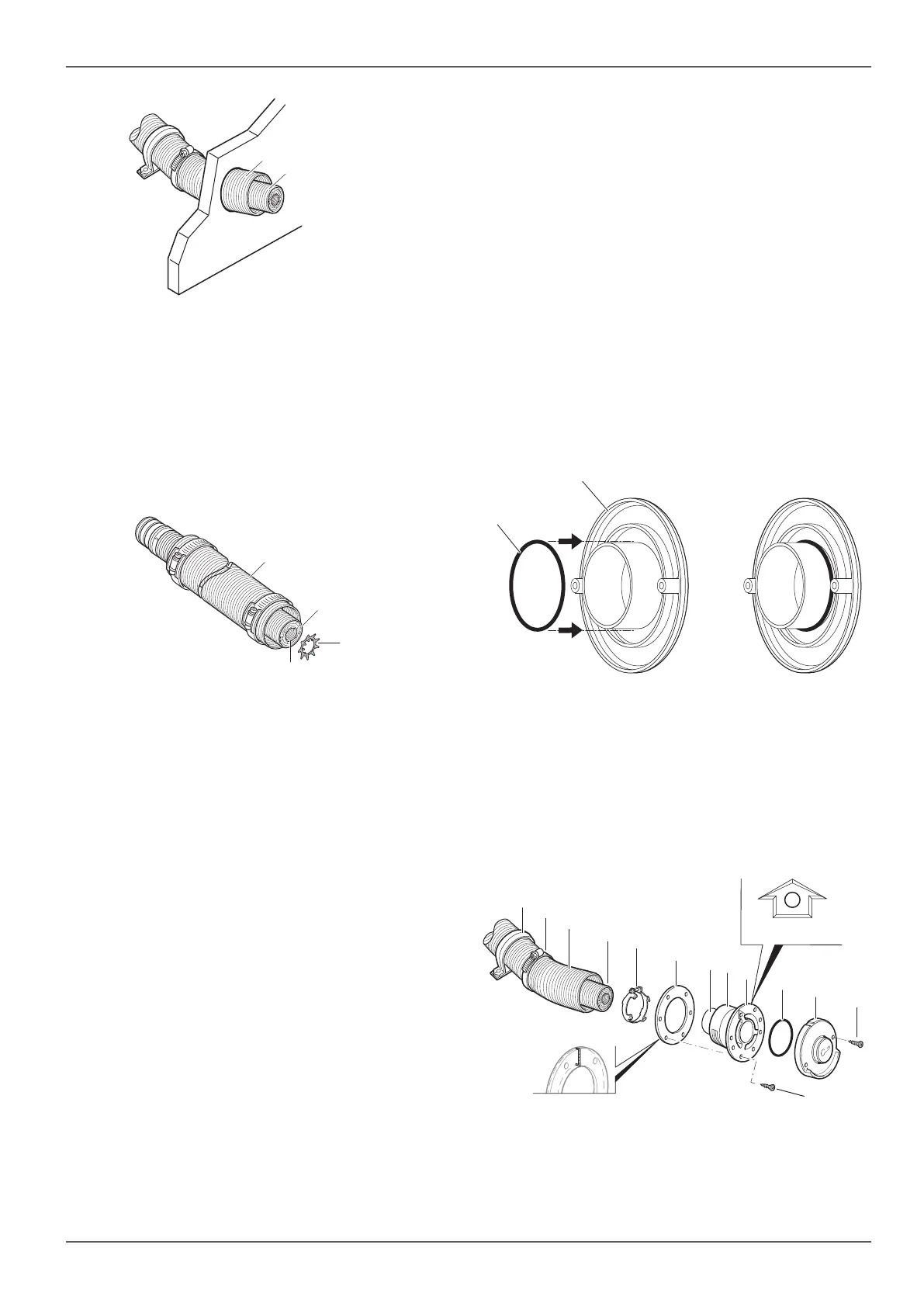
Fig. 11
For serial installation (fixed lengths), the length of the
exhaust gas sound muffler (Fig. 11-1) and the com-
bustion air intake duct (Fig. 11-2) can be determined
with a pattern. In individual cases the exhaust gas
sound muffler can be shortened. The Truma 35 mm
lock washer tool (part no. 34020-01282) is required
for this. Instructions how to shorten the duct kit are
provided with the 35 mm lock washer tool.
3
2
1
4
Fig. 12
When measuring the combustion air infeed, allow for
a minimum bending radius of 8 cm of the exhaust gas
sound muffler.
Installing the wall cowl
The wall cowls must be ordered separately.
To simplify installation, bend the exhaust duct ac-
cording to the installation position before installing it
on the wall cowl / heater.
NOTICE
Contamination from combustion deposits.
Because of the way a diesel heater works, com-
bustion residue can accumulate on the cowl
outer part.
Install only dark cowl outer parts (anthracite
or black).
Install the wall cowl (arrow pointing up) on an even sur-
face around which wind can flow from all sides.
Drill a hole with a diameter of 83 mm (line the cavi-
ties with wood around the cowl opening). Seal with
the enclosed wall cowl gasket (Fig. 14-6).
Use flexible body sealant on textured surfaces – do
not use silicone.
Before pushing the exhaust double duct through the
hole, slide the clamp (Fig. 14-2) over the duct.
Slide the wall cowl gasket (smooth side facing the
wall cowl, sealing lips facing the wall) onto thecowl
inner part (Fig. 14-9).
Slide the exhaust duct clamp (claws facing the wall
cowl) (Fig. 14-5) over the exhaust duct.
Slide the exhaust duct all the way onto the connec-
tion (Fig. 14-7) and screw in place.
Slide the air supply duct (Fig. 14-3) onto the serrated
connection (Fig. 14-8).
Fasten the combustion air intake duct onto the con-
nection with a hose clamp (Fig. 14-2).
Place the O-ring (Fig. 13-1) on the cowl outer part
(Fig. 13-2).
The O-ring is in the accessory kit of the Combi D.
1
Fig. 13
Attach the cowl inner part with six screws
(Fig. 14-12), attach the cowl outer part and screw
on with two screws (Fig. 14-12) (screws B 3.5 x 25,
included with delivery).
For lengths exceeding 60 cm, secure to the
wall with at least one clamp ZRS, Ø 80 mm
(partno. 39590-00) (Fig. 14-1).
TOP OBEN
11
5
6
10
8
2
1
3
4
9
12
7
12
TOP up
Fig. 14


 To Next Page