7
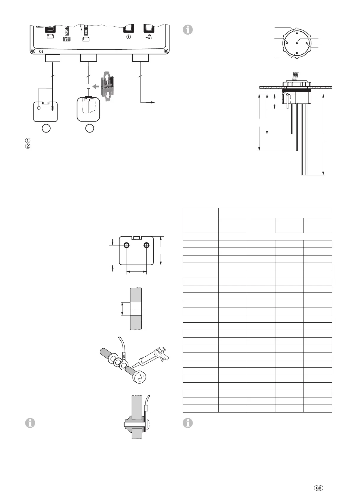
Connection
2
2 pol.
5 pol.
5
7 pol.
7
12
EM 16 IU
EM 30 IU
IIII
Made in GermanyMade in Germany
1/21/2
0 <11.5V<11.5V
Waste water tank
Fresh water tank
Install the cables to the tanks and power supply.
Connect the sensors to the panel and the power supply. The
plug connectors can only be inserted to the correct connection
when they are in the right position.
Ensure that all the catches lock into place.
Installation of the filling level sensors
Waste water tank
Establish the height of the
tank (external dimensions).
Establish and mark the posi-
tion of the boreholes for the
sensors.
H
min. 50 mm
4 H
9,5 – 10 mm
Drill 2 holes with a diameter
of 9.5 – 10 mm into the
waste water tank.
Smooth down the edges of
the boreholes.
Coat the screws with seal-
ing compound or an elastic
adhesive.
Assemble the measuring
sensors (1 wire of the 2-wire
line per measuring sensor).
Tighten the screws by hand.
Place each measuring sen-
sor into a borehole and
tighten with a screwdriver.
The edge of the rubber
seal is pressed against
the tank wall. The rubber
bulges inside thereby sealing
the borehole.
–
–
–
–
–
–
–
–
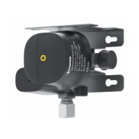
Fresh water tank
The supplied sensor
is designed for tank
heights of 150 mm to
380 mm external dimensions
and for vertical installation.
3/4
1/4
1/2
1/1
br
ws
gn
ge, gr
gn
br
ge
gr
ws
Establish the height of the
tank (external dimensions).
Drill the borehole with a
diameter of 38 ± 0.5 mm
at the highest point close
to the middle of the tank
and the cleaning opening.
If necessary, shorten the
measuring rods (see short-
ening table).
Insert the sensor into the
cleaning opening and
screw tight – observe the
correct position of the
sealing ring.
Tighten the nuts by hand.
Shortening table
Tank height
External
dimensions
[mm]
Measuring rod length [mm]
ws br gn ge, gr
380
Original length
370 22 81 170 260
360 22 78 165 253
350 22 76 160 245
340 22 73 155 238
330 22 71 150 230
320 22 68 145 223
310 22 66 140 215
300 22 63 135 208
290 22 61 130 200
280 22 58 125 193
270 22 56 120 185
260 22 53 115 178
250 22 51 110 170
240 22 48 105 163
230 22 46 100 155
220 22 45 95 148
210 22 44 90 140
200 22 43 85 133
190 22 41 80 125
180 22 39 75 118
170 22 38 70 110
160 22 36 65 103
150 22 35 60 95
The table applies for symmetrically shaped tanks.
The volume of non-symmetrical tanks needs to be
determined.
–
–
–
–
–