15
Before connecting and starting up the device, please be sure
to read the installation and operating instructions!
Glossary
AGM battery Lead-acid battery in which the
electrolyte is held in an Absorbed
Glass Mat.
Battery OPTIMA® YT S corresponds to an AGM battery.
Symbols used
Symbol indicates a possible hazard.
Note containing information and tips.
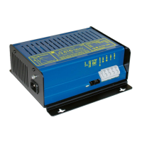
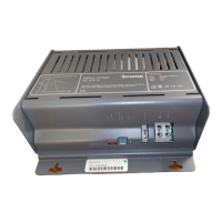
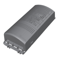
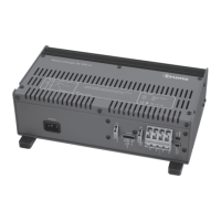
Solar Battery Charger SC 3
Operating instructions
Contents
Operating instructions
Glossary ............................................................................... 15
Symbols used ...................................................................... 15
Safety instructions ........................................................... 16
Intended use ..................................................................... 17
Use for incorrect purpose .................................................... 17
Battery care ...................................................................... 17
Device components ......................................................... 18
Operation ........................................................................... 18
Charging procedure ......................................................... 19
Switching the optional consumer output .................... 20
Operating indicator .......................................................... 20
Maintenance ..................................................................... 20
Technical data ................................................................... 21
Charge diagram ................................................................... 22
Disposal ............................................................................. 22
Declaration of conformity ............................................... 22
Truma manufacturer warranty declaration .................. 23
Installation instructions
Safety instructions ........................................................... 24
Scope of delivery .............................................................. 24
Assembly ........................................................................... 24
Connection ........................................................................ 25
Connection diagram ............................................................ 25
Taking into operation ...................................................... 25