Trumatic E 2400 (Australia)
Installation options
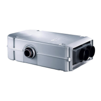
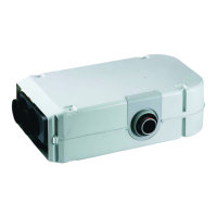
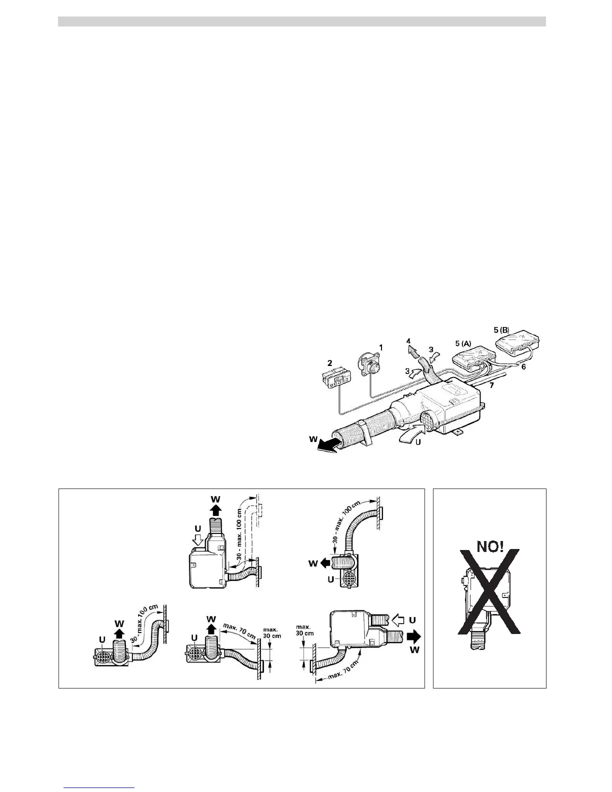
Installation example
1 Control panel
2 Time switch (accessories)
3 Combustion air
4 Flue gas
5 Electronic control units
6 Power supply
7 Gas connection
W Warm air
U Circulating air
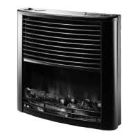
Installation inside the vehicle
with wall flue kit
1
Table of contents
Installation example .......................................................... 2
Symbols used ........................................................................ 3
Safety instructions ............................................................ 3
Important operating notes ............................................... 3
Operating instructions
Control panel with rotary switch .......................................... 4
Switching on the Heating ..................................................... 4
Switching on the Ventilation ................................................. 4
Switching off ......................................................................... 4
Green LED “Operation” ......................................................... 4
Fuses ..................................................................................... 4
Red LED “Failure” ................................................................. 4
Maintenance ....................................................................... 4
Accessories ......................................................................... 4
Technical data ..................................................................... 5
Dimensions ........................................................................... 5
Truma warranty policy ..................................................... 5
Trouble-shooting list ......................................................... 6
Installation instructions
Intended use .......................................................................... 7
Approval ................................................................................ 7
Regulations ........................................................................... 7
Choice of location .............................................................. 7
Exhaust duct ....................................................................... 8
Permissible duct lengths ....................................................... 8
Interior installation using the wall cowl kit ................. 8
Assembly of wall cowl .......................................................... 8
Fastening the appliance ........................................................ 8
Double cowl duct connection to the heating
appliance ............................................................................. 8
Warm air distribution and circulating air
return with interior installation ....................................... 9
Warm air distribution ............................................................ 9
Circulating air return ............................................................. 9
Fitting the control panel ................................................... 9
Installing the control panel with rotary switch ..................... 9
Fitting the electronic control units ............................... 10
Electrical connection 12 V .............................................. 10
Gas connection ................................................................. 10
Function check ................................................................. 11
Warning information ....................................................... 11
2