EasyManua.ls Logo

Truma Trumatic E 4000 User Manual

Truma Trumatic E 4000
92 pages
Go to English
To Next Page IconTo Next Page
Page #1 background imageLoading...
Page #1 background image
Gebrauchsanweisung Seite 2
Einbauanweisung Seite 9
Im Fahrzeug mitzuführen!
Operating instructions Page 17
Installation instructions Page 21
To be kept in the vehicle!
Mode d‘emploi Page 29
Instructions de montage Page 33
À garder dans le véhicule !
Istruzioni per l‘uso Pagina 42
Istruzioni di montaggio Pagina 46
Da tenere nel veicolo!
Gebruiksaanwijzing Pagina 55
Inbouwhandleiding Pagina 59
In het voertuig meenemen!
Brugsanvisning Side 68
Monteringsanvisning Side 72
Skal medbringes i køretøjet!
Instrucciones de uso Página 80
Instrucciones de montaje Página 84
¡Llévalas en el vehículo!
Trumatic E 4000 / E 4000 A ab 07 / 2010
Page 92
Trumatic E
1
3
5
7
9

Table of Contents

Other manuals for Truma Trumatic E 4000

Question and Answer IconNeed help?

Do you have a question about the Truma Trumatic E 4000 and is the answer not in the manual?

Truma Trumatic E 4000 Specifications

General IconGeneral
BrandTruma
ModelTrumatic E 4000
CategoryHeater
LanguageEnglish

Summary

Important Operating Notes

Mobile Heating Appliance Instructions

Operating Instructions

Control Panel with Slide Switch

Explains operation of the slide switch control panel.

Control Panel with Rotary Switch

Explains operation of the rotary switch control panel.

Switching on the Heating

Details the procedure for turning on the heating function.

Switching on the Ventilation

Details the procedure for turning on the ventilation function.

Switching Off the Appliance

Explains how to turn off the appliance.

LED Indicators and Fuses

Explains green operating and red failure LEDs, and fuse information.

Appliance Disposal

Guidelines for disposing of the appliance according to regulations.

Accessories

Control Unit VG 2

Control unit for driver's cabs and tank vehicles.

Outside Switch AS

Switch for external operation of the heater.

Acoustic Signalling Device ASM

Device for acoustic failure signals.

Time Switch ZUE

For pre-programming switch-on times.

Remote Sensor

Monitors room temperature independently of control panel.

Multiple Connector MSD

For connecting multiple accessories.

Direct Switch DIS 1

For high setting operation without temperature control.

Direct Fixed Temperature Switch DFS

For operating heater at fixed temperature.

Technical Data

Dimensions

Physical dimensions of the heater unit.

Declaration of Conformity

Manufacturer Information

Details about the manufacturer.

Device Identification

Model and type information of the device.

EC Directives Compliance

Lists EC directives the device meets.

Conformity Assessment Basis

Standards used for conformity assessment.

Auditing Body

Identifies the auditing authority.

Signatory Information

Details of the signatory.

Manufacturer's Warranty Terms

Warranty Case Definition

Defines what constitutes a warranty case.

Scope of Warranty

Outlines the duration and terms of the warranty.

How to Claim Warranty

Procedure for raising a warranty claim.

Trouble-shooting List

Installation Instructions

Intended Use

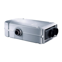
Specifies the intended applications for the appliance.

Approval Status

Details the appliance's approval status and relevant directives.

Regulations and Warranty

Outlines regulations and conditions for warranty claims.

Commercial Vehicle Installation Notes

Specific installation guidance for commercial vehicles.

Driver's Cab Installation Notes

Guidance for installing in vehicle driver's cabs.

Assembly Instructions for Trunk Heating Systems

Notes on Installation in Boats

Choice of Location and Duct Lengths

Permitted Duct Lengths: Wall Cowl

Specifies allowed duct lengths for inside installation with wall cowl.

Permitted Duct Lengths: Roof Cowl

Specifies allowed duct lengths for inside installation with roof cowl.

Permitted Duct Lengths: Under Floor Wall Cowl

Specifies allowed duct lengths for under-floor installation with wall cowl.

Installation of Wall Cowl

Double Cowl Duct Connection to Heating Appliance

Assembly of Condensate Trap

Assembly of Roof Cowl

Double Duct Connection to Heating Appliance

Under-floor Assembly with Wall Cowl Kit

Fastening the Heating Appliance

Outside Assembly with Cowl Pipes

Fastening the Heating Appliance (Outside)

Warm Air Distribution and Circulating Air Return (Interior)

Warm Air Distribution

Ensures clean heating air intake and proper distribution.

Warm Air Supply and Circulating Air Return (Outside)

Circulating Air Return

Details how circulating air is returned to the appliance.

Warm Air Supply and Return

Installation of warm air ducts for outside assembly.

Fitting the Control Panel

Installing Control Panel with Rotary Switch

Instructions for installing the control panel with a rotary switch.

Installing Control Panel with Slide Switch

Instructions for installing the control panel with a slide switch.

Fitting the Electronic Control Unit

Electrical Connection 12 V / 24 V

Gas Connection

Function Check

Warning Information