1. INTRODUCTION
This manual provides all safety information, operation instructions,
specifications and maintenance for the multimeter, which is compact,
hand-held and battery operated.
This instrument performs AC / DC voltage measurements, AC current,
resistance, audible continuity, diode, frequency, capacitance and
temperature.
It has 3-5/6 digits, is clamp digital multimeter and counts to 6 000
automatic range.
The design of the digital multimeter is in accordance with the
electronic measuring instruments, with over voltage category (CAT III
600 V, CAT II 1 000 V) and pollution degree 2.
To avoid possible electric shock or personal injury, and possible damage
to the Digital multimeter or the equipment under test, follow the
following rules:
Before using the Digital multimeter inspect the case. Do not use the
multimeter if damaged or part of the case has been removed. Look for
cracks or missing plastic Double check insulation around the
connectors.
Inspect the test probes for damaged insulation or exposed metal.
Check the test probes have continuity.
Do not apply more than the rated voltage as marked on the
multimeter, between the terminals or between any terminal and
grounding.
To prevent damage, the rotary switch must be placed in the correct
position and there must be no changes while the measurement is
being carried out.
Special care should be taken when the multimeter is working at an
effective voltage higher than 60 V in DC or 30 V RMS AC, as there is a
danger of electric shock.
Use the appropriate terminals, functions and range for the
measurements.
Do not use or store the multimeter in high temperature, humid
environments, near explosive and flammable products and strong
magnetic fields are present.
The performance of the multimeter may deteriorate after it gets wet.
When using test probes keep fingers behind the fingers guard.
Disconnect the feeding circuit and discharge all the high voltage
capacitors before testing resistance, continuity and diodes.
Replace the battery as soon as the battery indicator “ ” appears. With
a low battery, the multimeter might produce false readings that can lead
to electric shock and personal injury.
Remove the connection between the test probes and the circuit being
tested. Turn off the power to the multimeter before opening its housing.
When servicing the multimeter use only replacement parts of the same
model number or electrical specifications.
The internal circuit of the multimeter must not be altered at will to avoid
damaging it or having an accident.
Soft cloth and mild detergent should be used to clean the surface or the
multimeter when servicing. No abrasive and solvent should be used to
prevent the surface of the Digital multimeter from corrosion, damage
and accident.
The multimeter is suitable for indoor use.
Turn the multimeter power off when it is not in use and take out the
battery when not using for a long time. Constantly check the battery as
it may leak when it has been used for a long time. Replace the battery
immediately if leaking appears. A leaking battery will damage the
multimeter.
3. ELECTRICAL SYMBOLS
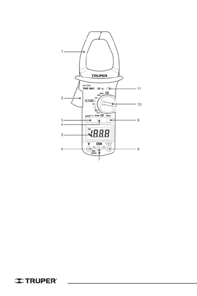
4. PARTS DESCRIPTION
1. Transformation clamp.
Receives the AC current flowing through the conductor.
2. Trigger
Press the lever to open the transformation clamp. Pressing the level with
one finger releases the clamp and closes it again.
3. Hz button / work
Press this button to select frequency (Hz) or duty cycle measurement in the
Hz position. If the knob is in the AC current position, you can measure
frequency.
4. Range Button
AC voltage / DC voltage, AC current and resistance measuring ranges can
be selected manually or automatically by pressing the range control
button. Press this button as follows to select the range control mode and
the required ranges.
 Loading...