• In a small mV range example, the multimeter may show an unstable
reading when the probes have not been connected to the load to be
measured. This is normal and will not affect the measurement.
• To avoid damage to the multimeter, do not measure a voltage exceeding
600 V (for DC voltage measurements) or 600 V (for AC measurement
under CAT III conditions and 1000 V for DC voltage) 750 V (for AC
voltage) under CAT II conditions
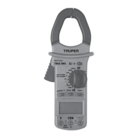
CURRENT MEASUREMENT
1. Set the switch Function / Range, in the range 60 A / 600 A /1 000 A
2. Pull the trigger to open the transfer clamps and hold only one conductor
as it is not possible to make measurements when two or three conductors
are held at the same time.
3. The reading on the display shows the current of the AC conductor.
RESISTANCE MEASUREMENT
1. Connect the BLACK test probe to the "COM" connector and the RED to
the ( ) connector (Note: The polarity of the red test probe is positive
"+").
2. Set the function switch to the range " "
3. Press the "RANGE" button and the measurement can be selected
manually.
4. Press the "SELECT" button to select the resistance mode measurement.
The symbol "MΩ" appears as an indicator.
5. Connect the test probes through the load to be measured.
6. Read the reading on the display.
• For resistance measurements >1 MΩ, it takes the multimeter a few
seconds to stabilize the reading. This is normal for high resistance
measurements.
• When the power input is not connected, e.g. in open circuit, the symbol
"OL" will be displayed as an overrange indicator.
• Before measuring the in-circuit resistance, confirm that the circuit being
tested has all power removed and that all capacitors are completely
discharged.
AUDIBLE CONTINUITY TEST
1. Connect the black test probe to the "COM" connector and the RED to the
" " connector. (Note: The polarity of the red test probe is positive
"+").
2. Set the function switch to the " " range.
3. Press the "SELECT" button to select the audible continuity test
selection mode. The " " symbol will appear as an indicator.
4. Connect the test probes through the load to be measured.
5. If the circuit resistance is less than 30 Ω, the interlocked buzzer will
buzz.
DIODE TEST
1. Plug the BLACK test probe into the "COM" connector and the RED
connector into " ". (Note: The polarity of the red test probe is
positive "+".
2. Set the function switch to the " " range
3. Press the "SELECT" button to select the continuity measurement mode.
The symbol " " will appear as an indicator.
4. Connect the red test lead to the anode of the diode to be tested and the
black test probe to the cathode.
5. The multimeter will show the direct voltage of the diode. If the
connections are reversed, "OL" will be shown on the display.
TEMPERATURE MEASUREMENT
1. Set the function range switch to the "TEMP" position.
2. Confirm that the polarity of the thermocouple probe is correct; place the
cold end (free end) of the thermocouple probe in the terminal (black on the
"COM" connector and red on the "ºC" connector).
3. Place the thermocouple on or in the object to be tested.
4. The temperature value is shown on the display in degrees Celsius (ºC).
5. Press the "SELECT" button, Fahrenheit and Celsius to convert the
values.
CAPACITANCE MEASUREMENT
1. Plug the BLACK test lead into the "COM" connector and the RED test lead
into the " " connector.
2. Set the function switch " " to the position. (NOTE: The polarity of
the RED test probe is positive "+").
3. Connect the test leads through the capacitor being measured and
confirm that the polarity of the connection is correct.
When the capacitance being measured is above 100 µF, it needs at least 5
seconds to stabilize the reading.
FREQUENCY MEASUREMENT (Automatic Range)
1. Set the range function switch to the required "Hz / Duty" position.
2. Plug the BLACK test probe into the "COM" connector and the RED test
probe into the " " connector. Note: Test probe polarity is positive
("+").
3. Connect the test probes through the load to be measured.
Do not apply more than 250 V RMS at the input. Voltages higher than 100 V
RMS may be indicated, but the reading may be out of range.
While using the clamp to test AC current, press the " " button and open
the clamp, the multimeter will display the frequency of the measured
current.
• The test temperature is displayed when the thermocouple probe is placed
in the test holes.
• The surrounding temperature is displayed when the sensor circuit is cut
off.
• The temperature limit measured by the thermocouple probe together with
the multimeter is 400 ºC maximum in short periods, in case you need to
measure higher temperatures you should acquire a thermocouple probe
with a higher capacity.
7. AUTOMATIC SHUT OFF
If the multimeter is not operated for about 15 minutes, it turns off
automatically. To turn it back on, just turn the range switch
8. BATTERY REPLACEMENT
If the " " symbol appears on the display, it indicates that the battery needs
to be changed. Remove the screws and open the back of the housing.
Replace the battery with a new one.
Uses 1 6F22 9V DC Carbon-Zinc battery (included).
NOTE
NOTE
NOTE
 Loading...