• In a small mV range example, the multimeter may show an unstable
reading when the probes have not been connected to the load to be
measured. This is normal and will not affect the measurement.
• To avoid damage to the multimeter, do not measure a voltage exceeding
600 V (for DC voltage measurements) or 600 V (for AC measurement
under CAT III conditions and 1000 V for DC voltage) 750 V (for AC
voltage) under CAT II conditions
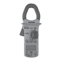
CURRENT MEASUREMENT
1. Set the switch Function / Range, in the range 60 A / 600 A /1 000 A
2. Pull the trigger to open the transfer clamps and hold only one conductor
as it is not possible to make measurements when two or three conductors
are held at the same time.
3. The reading on the display shows the current of the AC conductor.
RESISTANCE MEASUREMENT
1. Connect the BLACK test probe to the "COM" connector and the RED to
the ( ) connector (Note: The polarity of the red test probe is positive
"+").
2. Set the function switch to the range " "
3. Press the "RANGE" button and the measurement can be selected
manually.
4. Press the "SELECT" button to select the resistance mode measurement.
The symbol "MΩ" appears as an indicator.
5. Connect the test probes through the load to be measured.
6. Read the reading on the display.
• For resistance measurements >1 MΩ, it takes the multimeter a few
seconds to stabilize the reading. This is normal for high resistance
measurements.
• When the power input is not connected, e.g. in open circuit, the symbol
"OL" will be displayed as an overrange indicator.
• Before measuring the in-circuit resistance, confirm that the circuit being
tested has all power removed and that all capacitors are completely
discharged.
AUDIBLE CONTINUITY TEST
1. Connect the black test probe to the "COM" connector and the RED to the
" " connector. (Note: The polarity of the red test probe is positive
"+").
2. Set the function switch to the " " range.
3. Press the "SELECT" button to select the audible continuity test
selection mode. The " " symbol will appear as an indicator.
4. Connect the test probes through the load to be measured.
5. If the circuit resistance is less than 30 Ω, the interlocked buzzer will
buzz.
DIODE TEST
1. Plug the BLACK test probe into the "COM" connector and the RED
connector into " ". (Note: The polarity of the red test probe is
positive "+".
2. Set the function switch to the " " range
3. Press the "SELECT" button to select the continuity measurement mode.
The symbol " " will appear as an indicator.
4. Connect the red test lead to the anode of the diode to be tested and the
black test probe to the cathode.
5. The multimeter will show the direct voltage of the diode. If the
connections are reversed, "OL" will be shown on the display.
TEMPERATURE MEASUREMENT
1. Set the function range switch to the "TEMP" position.
2. Confirm that the polarity of the thermocouple probe is correct; place the
cold end (free end) of the thermocouple probe in the terminal (black on the
"COM" connector and red on the "ºC" connector).
3. Place the thermocouple on or in the object to be tested.
4. The temperature value is shown on the display in degrees Celsius (ºC).
5. Press the "SELECT" button, Fahrenheit and Celsius to convert the
values.
CAPACITANCE MEASUREMENT
1. Plug the BLACK test lead into the "COM" connector and the RED test lead
into the " " connector.
2. Set the function switch " " to the position. (NOTE: The polarity of
the RED test probe is positive "+").
3. Connect the test leads through the capacitor being measured and
confirm that the polarity of the connection is correct.
Póliza de garantía
Warranty Policy
MUT-202 10404
03-2023
Truper, S.A. de C.V.
www.truper.com
Garantía. Duración: 1 año. Cobertura: piezas, componentes y mano de obra
contra defectos de fabricación o funcionamiento, excepto si se usó en
condiciones distintas a las normales; cuando no fue operado conforme
instructivo; fue alterado o reparado por personal no autorizado por Truper
®
.
Para hacer efectiva la garantía presente el producto, póliza sellada o factura
o recibo o comprobante, en el establecimiento donde lo compró o en
Corregidora 35, Centro, Cuauhtémoc, CDMX, 06060, donde también podrá
adquirir partes, componentes, consumibles y accesorios. Incluye los gastos
de transportación del producto que deriven de su cumplimiento de su red
de servicio. Tel. 800-018-7873. Made in/Hecho en China. Importador Truper,
S.A. de C.V. Parque Industrial 1, Parque Industrial Jilotepec, Jilotepec,
Edo. de Méx. C.P. 54257, Tel. 761 782 9100.
Warranty. Duration: 1 year. Coverage: parts, components and workmanship
against manufacturing or operating defects, except if used under conditions
other than normal; when it was not operated in accordance with the
instructive; was altered or repaired by personnel not authorized by Truper
®
.
To make the warranty valid, present the product, stamped policy or invoice
or receipt or voucher, in the establishment where you bought it or in
Corregidora 35, Centro, Cuauhtémoc, CDMX, 06060, where you can also
purchase parts, components, consumables and accessories. It includes the
costs of transportation of the product that derive from its fulfillment of
its service network. . Phone number 800-018-7873. Made in China. Imported
by Truper, S.A. de C.V. Parque Industrial 1, Parque Industrial Jilotepec,
Jilotepec, Edo. de Méx. C.P. 54257, Phone number 761 782 9100.
Sello del establecimiento comercial / Stamp of the business
Fecha de entrega / Delivery date
 Loading...