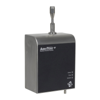
2–4 AeroTrak™ Remote Airborne Particle Counters
Alarm Contact: Terminals 6–7
The alarm contact is used to indicate an alarm condition. The alarm
contact closure is normally open. The contact closes upon an alarm,
which could be a high particle alarm, a laser error, a detector error, or a
flow error, depending on the configuration of the particle counter.
Channel 1 Particle Counts: Terminals 5:2
Channel 2 Particle Counts: Terminals 4:2
These are 4-20 mA outputs that correspond to the particle counts for 2
channels on the remote particle counter. These are configured using
dipswitches found on the circuit board shown when the internal electrical
connections are visible. Configuration consists of channel selection,
linear/log, and scale. See
Appendix A for a detailed description of options.
Status Information: Terminals 3–2
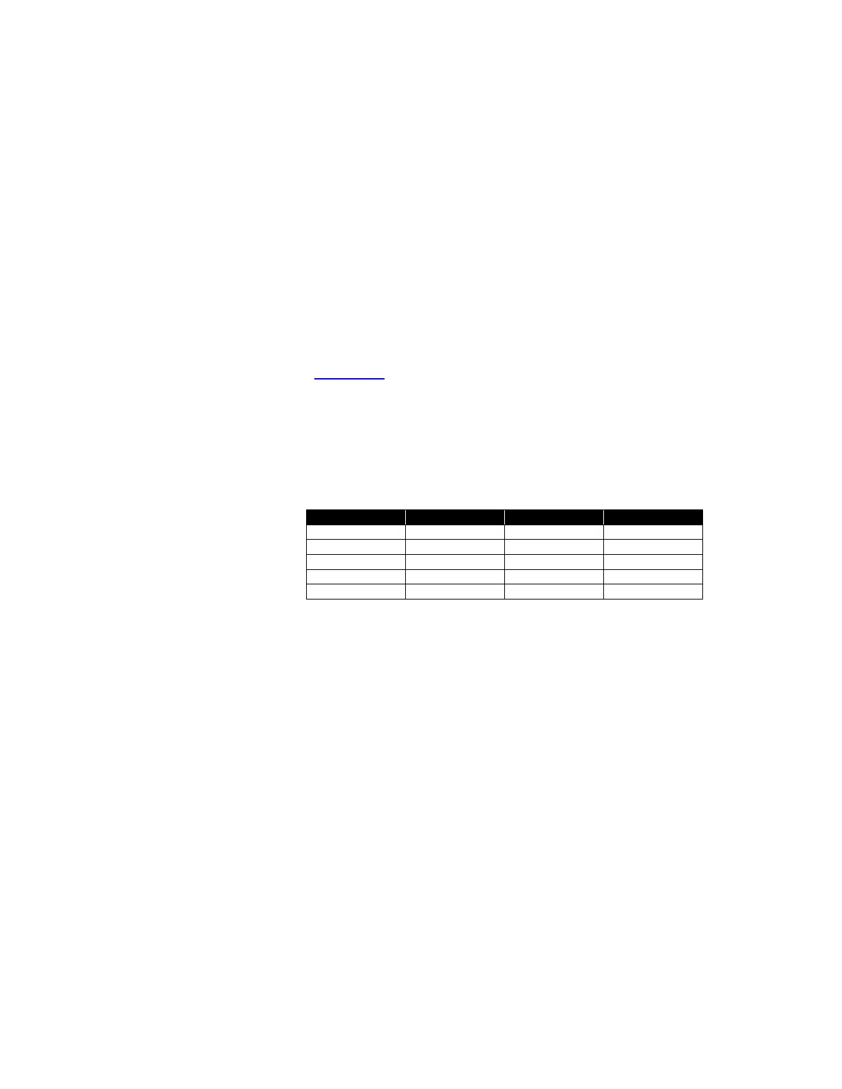
This is a 4-20 mA output that provides additional status information about
the remote’s flow and laser condition. The output will go to a nominal
current value that corresponds to the condition listed below.
 Loading...