p. 5 of 20
Pressure Controller Installation
Pressure Controller Rough-in
Select the mounting location of the pressure controller. The construction plans normally show the
mounting location. If no location is specified, then the unit is typically installed as shown in Figure 1.
Alternate mounting locations are nurses’ station, other staff areas, etc.
Install a standard triple gang electrical box (6” 4”). The electrical box must be installed level and flush
with the wall surface.
Use appropriate firestop material, per local codes, if electrical box is to be installed in a fire barrier.
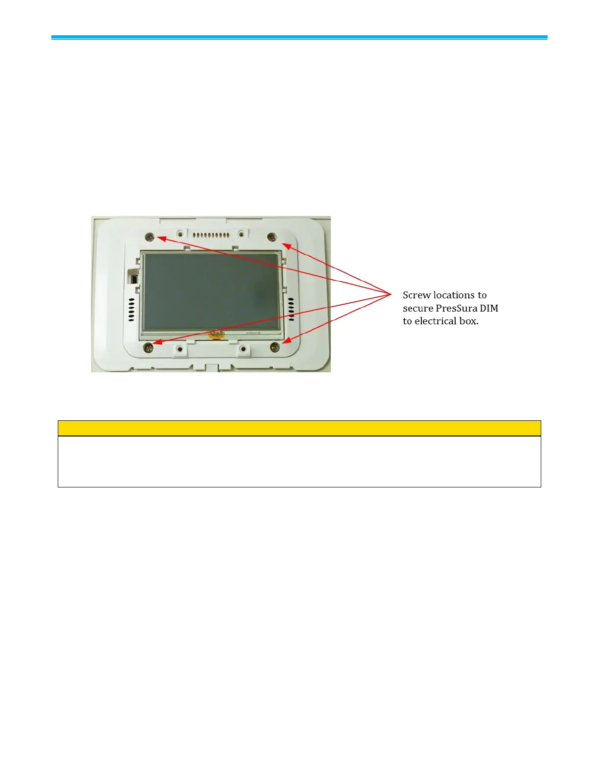
Screw PresSura DIM to electrical box (Figure 7).
Figure 7: Pressure Controller Mounting
Pressure Controller Wiring
WARNING
Do not connect more than 24 VAC to any terminal.
Do not apply voltage to the RS-485 output, BACnet output, analog output, or control output. Severe
damage may occur to the unit if voltage is applied.
Wiring Recommendations
TSI recommends stranded wire.
Comply with local and national electrical codes.
Follow good wiring practices:
o Do not run control wiring in the same conduit or wireway as power wiring.
o Control cables should cross power cables at a 90-degree angle.
o Use a consistent color code to maintain polarity.
o Control signals require “home run” wiring / star configuration. Do not daisy-chain control wires or
use a series configuration.
o Use daisy-chain configuration for connecting the nurses’ station to monitors and controllers.
Remove the connectors from the back of the pressure controller.
Refer to the wiring diagrams, Figure 8 to Figure 28 for proper wiring installation.
If additional options need to be wired, refer to building prints for proper wiring diagram.
Plug the connectors back into the pressure controller.
Carefully push the wires into the electrical box and mount the pressure controller. Install four screws to
hold pressure controller firmly to base. Install cover and slide left to hide display.

 Loading...