bout the Compact Frontal Machine (CFM-500)
ongratulations on your new purchase of the Compact Frontal
achine (CFM-500). This gym is capable of a variety of different
xercises, as-well-as, smooth and user-friendly adjustment
atures. In addition, this gym has been designed to meet the
eeds and performance requirements for a suitable home exercise
achine. We hope you are completely satisfied with this product
nd wish you many years of enjoyment.
uff Stuff Equipment
his Tuffstuff product has been built to precise quality standards
nd has been carefully packaged to ensure that damage will not
ccur during shipment.
The Home Lifetime Warranty and signature
dicating final inspection has been conducted by our line foreman,
an expression of our confidence in the completeness, the
aterials, and workmanship of this product.
arranty
EE A COPY OF WARRANTY ON BACK PAGE.
egistration Card
o avoid unnecessary delays in warranty service and to insure that
permanent record of your purchase is on file with our factory, be
ure to complete the warranty registration card and send it to Task
dustries today.
A Note provides information necessary to properl
complete a procedure or information which will mak
the procedure easier to understand.
A Caution provides a special procedure or specia
steps which must be taken while completing th
procedure where the Caution is found. Not followin
a Caution can result in damage to the equipment.
A Warning provides a special procedure or specia
steps which must be taken while completing th
procedure where the Warning is found. Not followin
a Warning can result in personal injury.
Assembly Notes
1. Read and follow each step of this Assembly Instruction Manual i
sequence. Do not skip ahead, as it will result in an imprope
assembly or in having to disassemble parts later.
2. During the assembly of this unit you will be instructed to leav
some Hex Head Cap Screws loosely fastened. Naturally, the
will be fully fastened later in the assembly process. This is don
to prevent any difficulty with alignment of some parts during thi
assembly.
Loosely Fasten provides a instruction to loosel
fasten (ex: hand tighten) a hardware assembly only.
This instruction is intended for the alignment o
hardware components during the assembly process.
Fully Fasten provides a instruction to fully fasten
(
ex: completely tighten) a hardware assembly.
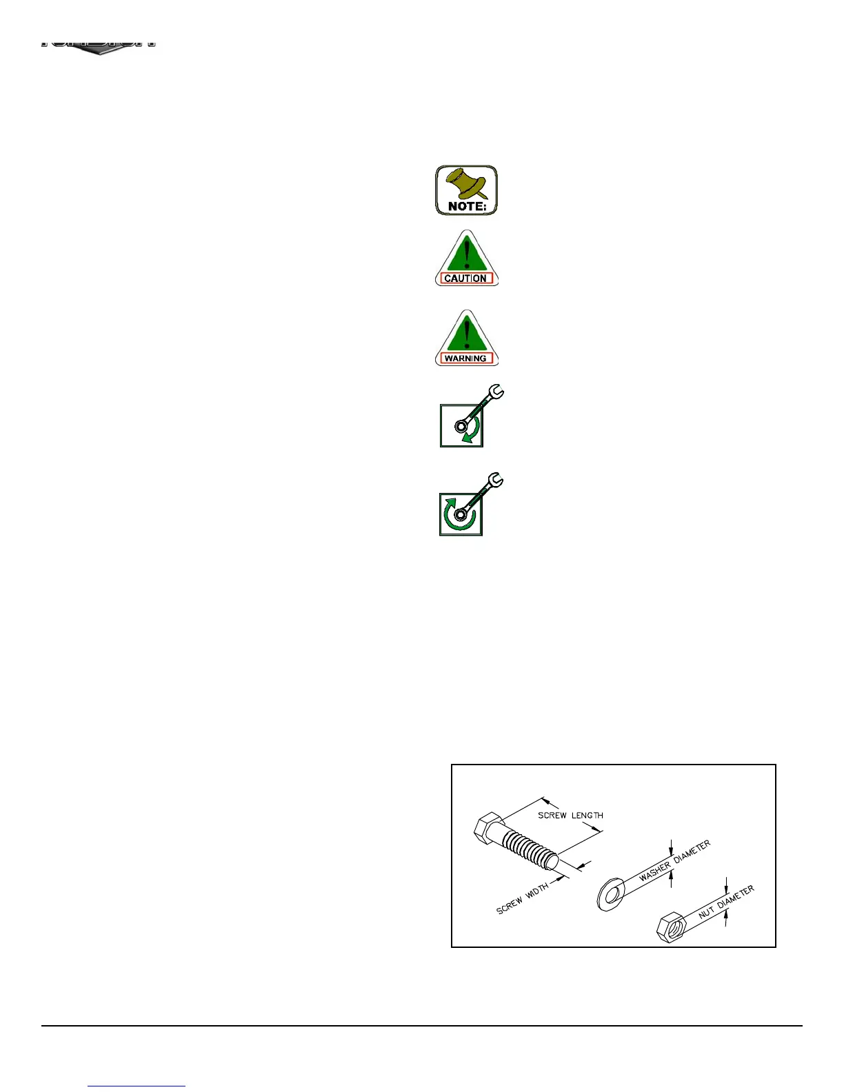
Hardware Measurement Diagram
CFM-500 Compact Frontal Machin
1
About the Icons
The icons displayed in this Owner’s Manual are used to facilitat
the correct assembly and safe use of this Product, as-well-as t
prevent injury to yourself or anyone else.
LOOSELY FASTEN
FULLY FASTEN
n
ro
uc
on
Note: Due to continuing product improvements, specifications and designs are subject to chang
without notice.
Even though we have prepared this manual with extreme care, neither the publisher nor the autho
can accept responsibility for any errors in, or omission from, the information given.
pecifications
Maximum Wt. Capacity - 200 Lbs. Fixed
Total Machine Weight - 430 Lbs.
Footprint (LWH) - See Front Cover
rior to the Assembly of the CFM-500
. We advise you to consult your local Tuff Stuff retailer if you
should have a question or problem regarding the proper
assembly of this Compact Frontal Machine (CFM-500).
. Consider the complete surface area of the CFM-500. Use the
overhead view on the front page for designing your layout before
assembling. Once the CFM-500 has been fully assembled it will
be heavy and difficult to move, therefore you should assemble
the CFM-500 in the area where it is to be used upon completion.
. It is recommended that another person assist you with the
assembly this unit.
. Neatly organize and identify all parts according to the Parts List
on page 1 8 and the Exploded View Diagram on page 17.
Tool Requirements
1. One 9/16” combination wrench
2. One 3/4” combination wrench
3. One 7/8” combination wrench
. One 1/2” combination wrench
5. Two 7/16” combination wrenches
6. One ratchet
7. One 9/16” socket
8. One 3/4” socket
9. One rubber mallet
0.Windex or household glass cleaner
1.One can silicone spray/ teflon spray lubricant
2.Multi-purpose grease
3.Measuring tape
4.Masking tape
5.Utility knife