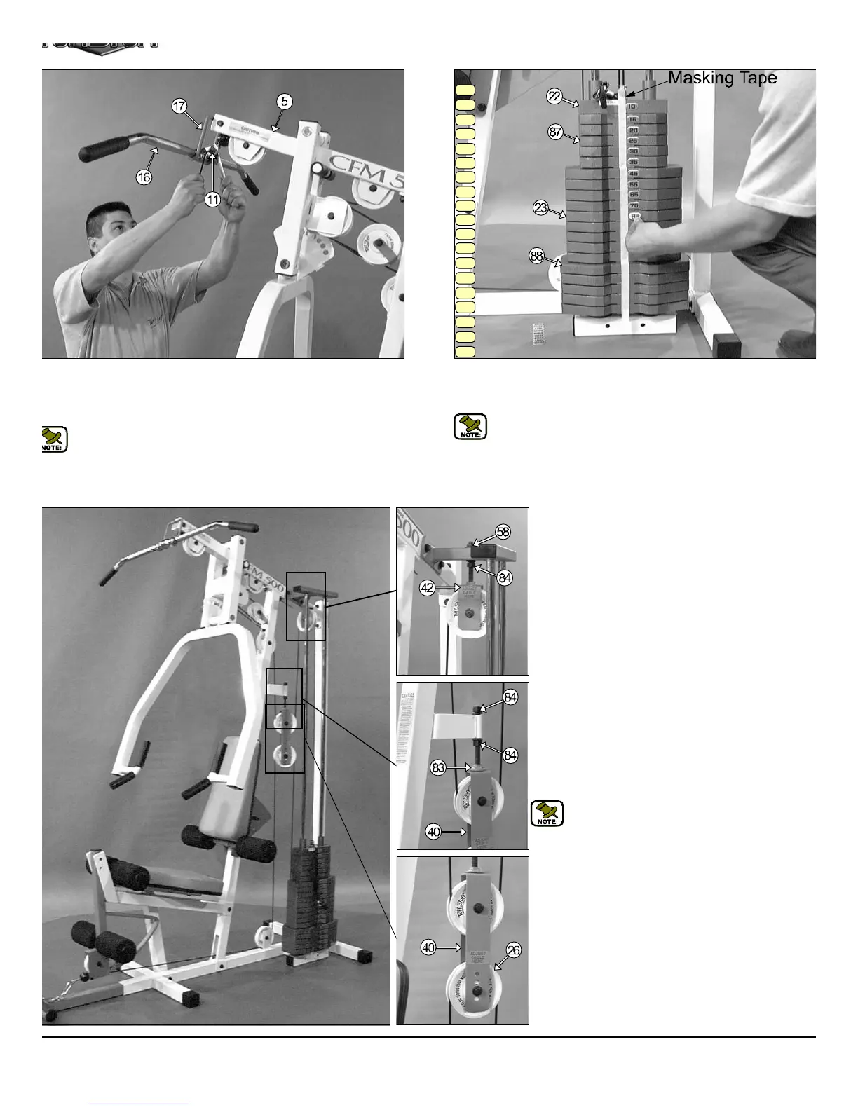
IG. 51 Connect the Lat Bar (#16) to the Lat Cable (#11) using one
trap Bracket (#74), one Shoulder Bolt 3/8 X 3/4 (#70) and one Nylon
sert Lock Nut 5/16-16 (#9). Use the Supplied 3/16” Hex Key (#79) and
1/2” combination wrench to fasten this assembly properly.
Note: Refer to Fig. A on page 16 for further illustration of this
assembly.
15
20
25
30
35
45
55
65
75
85
95
105
115
125
140
155
170
185
200
Adjustment for:
Adjustable Stopper (#83)
1. Loosen both Regular Hex Nuts 1/2-13 (#84)
2. Adjust the Adjustable Stopper (#83) to make conta
with the Adjustable Double Pulley Brkt. (#40)
3. Re-tighten both Regular Hex Nuts 1/2-13 (#84)
complete the adjustment.
Note: Be sure that the Adjustable Double Pull
Brkt. (#40) is always resting on the Adjustabl
Stopper (#83).
Cable Adjustment for:
Adjustable Double Pulley Brkt. (#40)
1. Remove the hardware from the Nylon Pulley 4 1/2 R
(#26) located at one of the four holes on the Adjustab
Double Pulley Brkt. (#40).
2. By interchanging the Nylon Pulley 4 1/2 Rd. (#26) t
the next adjustment hole, this will make a one inch c
ble adjustment.
3. Re-tighten the hardware for Nylon Pulley 4 1/2 R
(#26) to complete the cable adjustment.
FIG. 52 To attach the Decal Weight Numbers (#86) we recommen
using a piece of masking tape as a guide to vertically center the Dec
Weight Numbers (#86), as shown above.
Note: Attach the Decal Weight Numbers (#86) in the numerical s
quence as illustrated above.
CFM-500 CABLE ADJUSTMENTS DIAGRAM
Cable Adjustment for:
Adjustable Pulley Bracket (#42)
1. Loosen the bottom Regular Hex Nut (#84)
2. Adjust the top Nylon Insert Jam Lock Nut (#58) to giv
the cable proper tension.
3. Re-tighten the bottom Regular Hex Nut (#84)
complete the cable adjustment.
CFM-500 Compact Frontal Machin
15