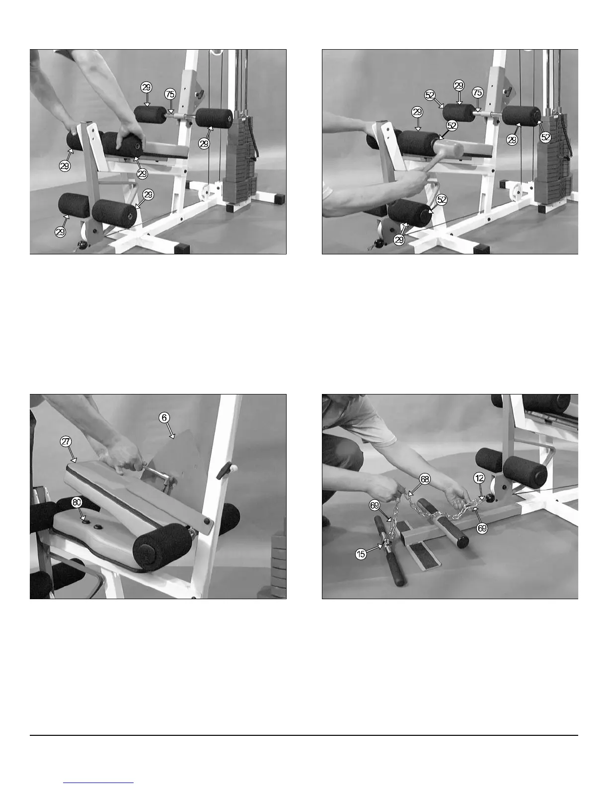
IG. 49 Mount the Back Pad (#27) to the Back Pad Bracket (#6) and
cure into place using two Hex Head Cap Screws 3/8-16 X 1 (#32) and
o Bumper Washers 3/8 (#81). Cap-off the two Bumper Washers 3/8
81-Not shown) using two Bumper Caps Black (#80-Not shown).
ote: Refer to Fig. 54 on page 19 for further clarification of this assembly.
FIG. 50 Locate the Coil Chain (#68) and two Snap Links (#69) an
attach them to the Low Row Bar (#15) and to the Leg Extension Cabl
(#12) as shown above.
FIG. 48 Next, using a rubber mallet, insert one Foot Roll Plastic En
Cap 1” (#52) to each end of the three tubes, as shown above. Refer t
the Exploded View Diagram on page 17 for further clarification of this a
sembly.
IG. 47 Attach one Foam Foot Roll 7 X 4 X 1 (#29) to each end of the
ree tubes, as shown above. Refer to the Exploded View Diagram on
ge 17 for further clarification of this assembly.
FM-500 Compact Frontal Machine
14
wner
s
anua
:
ssem
y
ns
ruc
on