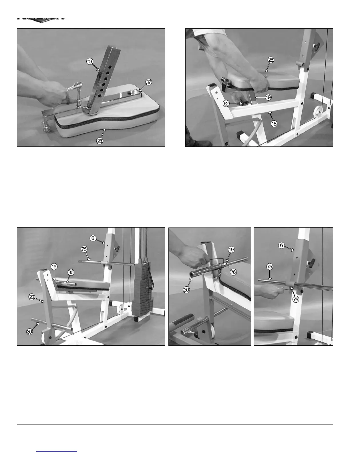
FIG. 44 Insert the Bench Press Adj. Seat Frame (#19) into the Leg E
tension Bench Frame (#18), in the position as shown above. Be sure
release the push-pull pin 1/2” (#64) as you begin to insert the assemble
Bench Press Adj. Seat Frame (#19) into the Leg Extension Benc
Frame (#18).
FIG. 46 Secure, both, the Foot Roll Tube 1 X 16 (#30) on the Benc
Press Adj. Seat Frame (#19) and the Foot Roll Tube 1 X 23 3/4 (#75)
the Adjustable Back Pad Bracket (#6) into place using two Set Scre
1/4-20 X 1/4 (#76). Use the supplied Hex Key 1/8 (#77) for securing th
Set Screws 1/4-20 X 1/4 (#76) into the threaded socket located on th
Bench Press Adj. Seat Frame (#19) and the Adjustable Back Pa
Bracket (#6).
IG. 43 Next, insert one Plastic Insert Cap 1 X 2 (#37) into the tube-
dof the Bench Press Adj. Seat Frame (#19). Next, locate the Seat
ad (#28) and attach it to the Bench Press Adj. Seat Frame (#19), as
own above, using two Hex Head Cap Screws 3/8-16 X 1 3/4 (#50) and
o Flat Washers SAE 3/8” (#45).
IG. 45 Next, inset on Foot Roll Tube 1 X 16 (#30) into the receptacle
cated on the end of the Bench Press Adj. Seat Frame (#19). Then, in-
rt one Foot Roll Tube 1 X 16 (#30) into the receptacle located on the
eg Extension Arm (#20). Next, insert the Foot Roll Tube 1 X 23 3/4
75) into the receptacle located on the Adjustable Back Pad Bracket
6), as shown above. Be sure all these tubes are centered at the recep-
cles from end-to-end.
CFM-500 Compact Frontal Machin
13