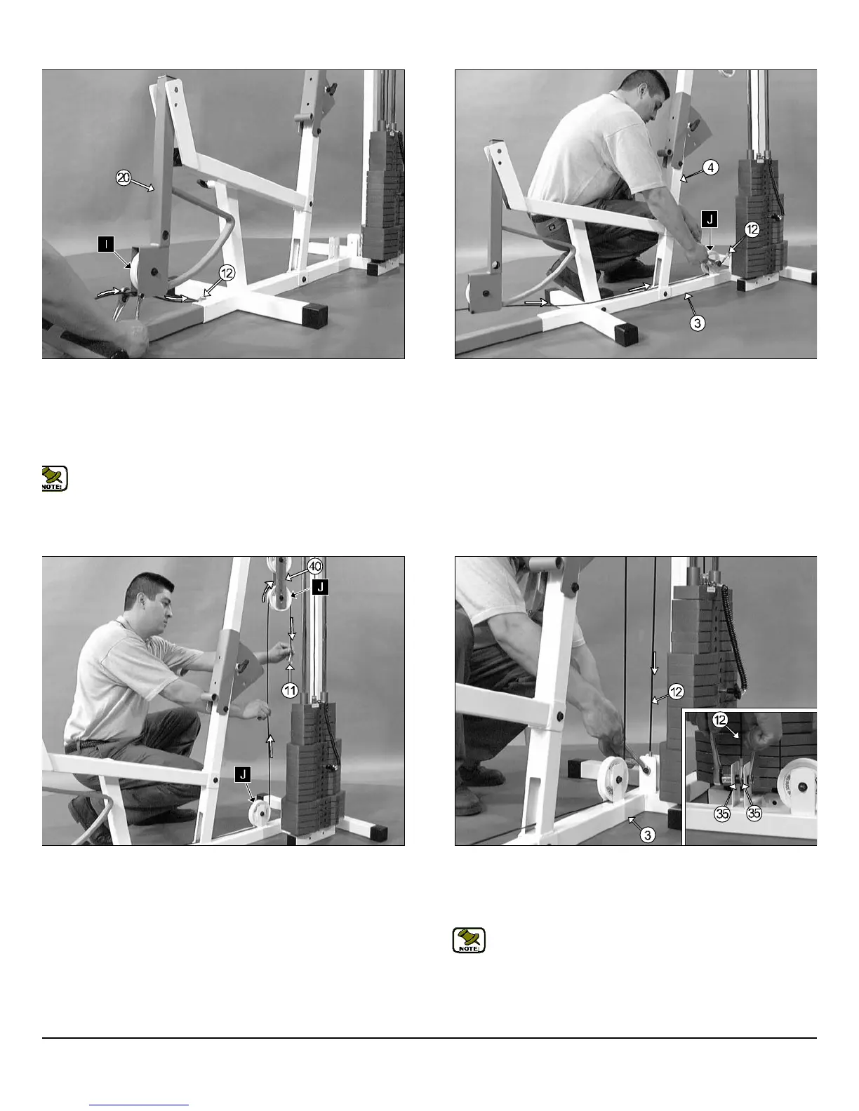
IG. 39 Next, install a Nylon Pulley 4 1/2 Rd. (#26-Labeled I) into the
lley bracket located on the Leg Extension Arm (#20) and secure it into
ace using one Hex Head Cap Screw 3/8-16 X 1 3/4 (#50), two Flat
ashers SAE (#45) and one Nylon Insert Jam Lock Nut 3/8-16 (#48).
ext, route the Leg Extension Cable (#12) under the Nylon Pulley 4 1/2
d. (#26-Labeled I), then secure it into place using one Hex Head Cap
crew 1/4-20 X 1 1/2 (#63) and one Nylon Insert Lock Nut 1/4-20 (#64).
Note: Refer to Fig. C on page 16 for further illustration of this
assembly.
FIG. 40 Next, route the Leg Extension Cable (#12) through the Fro
Upright (#4), then under the Nylon Pulley 4 1/2 Rd. (#26-Labeled J
Secure the Nylon Pulley 4 1/2 Rd. (#26-Labeled J) into place using on
Hex Head Cap Screw 3/8-16 X 1 3/4 (#50), two Flat Washers SAE 3/
(#45) and one Nylon Insert Jam Lock Nut 3/8-16 (#48).
IG. 41 Lift the end of the Leg Extension Cable (#12) and route it
rough the Adjustable Double Pulley Bracket (#40) and over the Nylon
ulley 4 1/2 Rd. (#26-Labeled K), as shown above.
FIG. 42 Connect the looped end of the Leg Extension Cable (#12)
the pulley bracket located on the Base Frame (#3), as shown abov
Secure this assembly using one Hex Head Cap Screw 3/8-16 X 1 3/
(#50), two Flat Washers SAE 3/8 (#45), two Nylon Spacers 3/8 X 3
(#35) and one Nylon Insert Jam Lock Nut 3/8-16 (#48).
Note: Refer to Fig. D on page 16 for further illustration of th
assembly.
FM-500 Compact Frontal Machine
12
wner
s
anua
:
ssem
y
ns
ruc
on