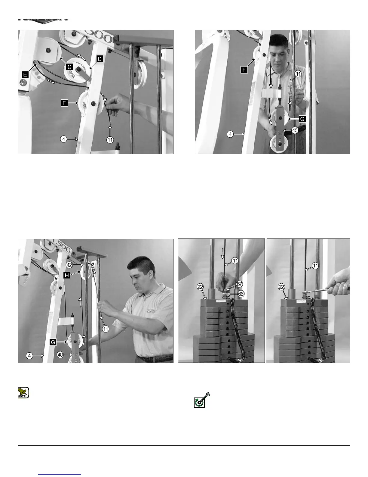
. 35 Next, route the Lat Cable (#11) through the Front Upright
) and over the Nylon Pulley 4 1/2 Rd. (#26-Labeled F), as shown.
FIG. 36 Next, route the Lat Cable(#11) through the Adjustabl
Double Pulley Bracket (#40) and under the Nylon Pulley 4 1/2 Rd. (#2
Labeled G), as shown above.
IG. 37 Next, route the Lat Cable (#11) through the Adjustable Pulley
racket (#42) and over the Nylon Pulley 4 1/2 Rd. (#26-Labeled H), as
own above.
Note: Use Cable Mapping Diagram on page 16 for further detailed
illustration of the Lat Cable (#11) routing.
FIG. 38 Next, attach the Lat Cable (#11) to the Top Plate/ Select
Bar (#22) and secure it into place using one Split Bolt 1/2-13 (#67) an
one Split Washer 1/2 (#66). Refer to Fig. B on page 16 for furth
illustration of this hardware assembly.
Fully Fasten: Proceed to fully fasten this hardware assembly.
CFM-500 Compact Frontal Machin
11
FULLY FASTEN