FIG. 32 Next, route the Lat Cable (#11) over the Nylon Pulley 4 1/
Rd. (#26-Labeled C), as shown above.
Note: Use Cable Mapping Diagram on page 16 for further detaile
illustration of the Lat Cable (#11) routing.
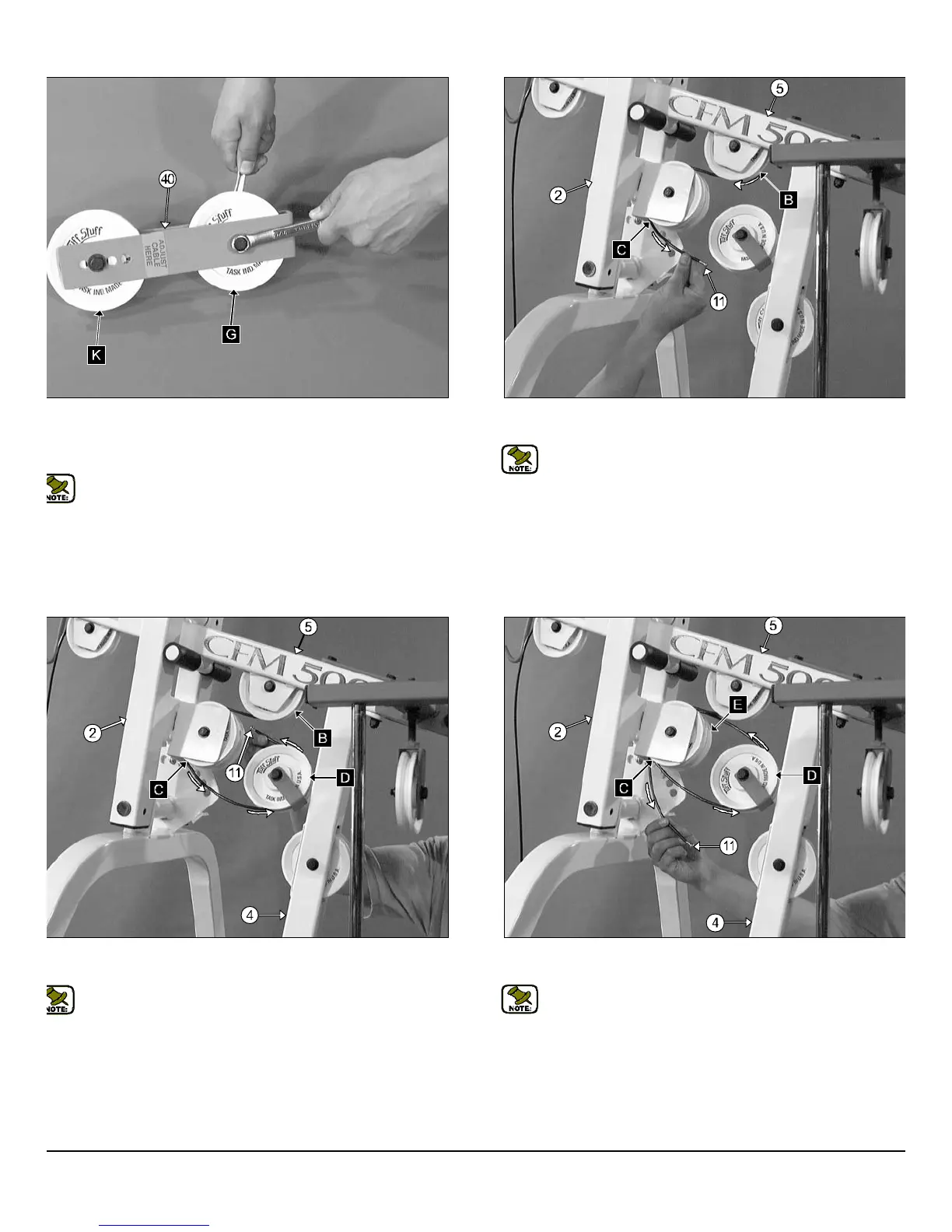
IG. 33 Next, route the Lat Cable (#11) up and over the Nylon Pulley 4
2 Rd. (#26-Labeled D), as shown above.
Note: Use Cable Mapping Diagram on page 16 for further detailed
illustration of the Lat Cable (#11) routing.
FIG. 34 Next, route the Lat Cable (#11) over the Nylon Pulley 4 1/
Rd. (#26-Labeled E), as shown above.
Note: Use Cable Mapping Diagram on page 16 for further detaile
illustration of the Lat Cable (#11) routing.
ig. 31 Assemble the Adjustable Double Pulley Bracket (#40) using
o Nylon Pulleys 4 1/2 Rd. (#26-Labeled G, K), two Hex Head Cap
crews 3/8-16 X 1 3/4 (#50), four Flat Washers SAE 3/8 (#45) and two
ylon Insert Jam Lock Nuts 3/8-16 (#48).
Note: The four holes on the Adjustable Double Pulley Bracket
(#40) are used to adjust the cable tension once the cable routing
has been completed.
FM-500 Compact Frontal Machine
10
wner
s
anua
:
ssem
y
ns
ruc
on