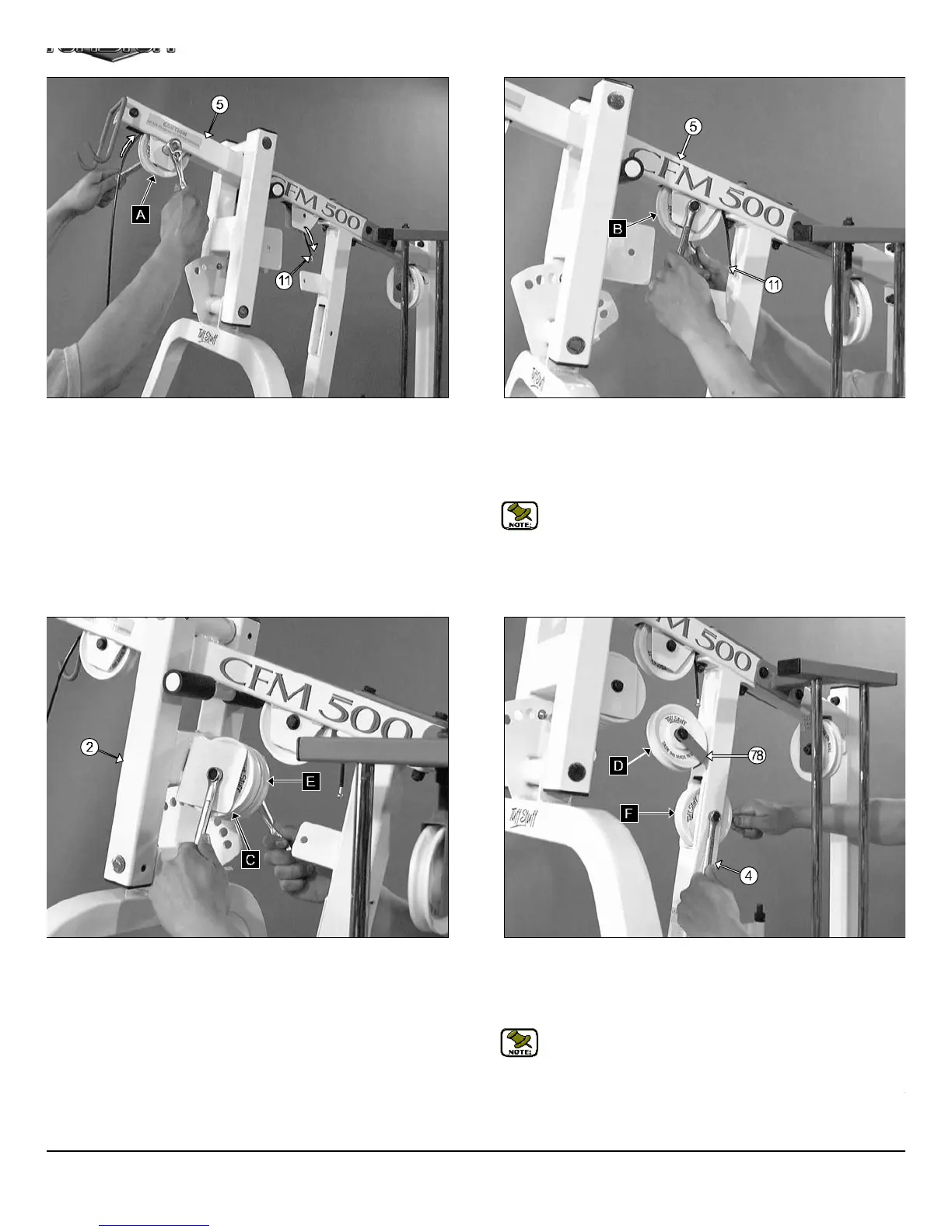
IG. 27 Insert one Nylon Pulley 4 1/2 Rd. (#26-Labeled A) into the
lley bracket of the Top Pulley Housing (#5) and secure it into place
ing one Hex Head Cap Screw 3/8-16 X 1 3/4 (#50), two Flat Washers
AE 3/8 (#45) and one Nylon Insert Jam Lock Nut 3/8-16 (#48). Next,
gin routing the Lat Cable (#11) over the Nylon Pulley 4 1/2 Rd. (#26-
beled A) and into the tube of the Top Pulley Housing (#5), as shown
ove.
FIG. 28 Next, route the end of the Lat Cable (#11) through the othe
pulley bracket located on the Top Pulley Housing (#5). Then insert
Nylon Pulley 4 1/2 Rd. (#26-Labeled B) into this pulley bracket and secu
the Nylon Pulley 4 1/2 Rd. (#26-Labeled B) into place using one Hex Hea
Cap Screw 3/8-16 X 1 3/4 (#50), two Flat Washers SAE 3/8 (#45) and on
Nylon Insert Jam Lock Nut 3/8-16 (#48).
Note: Use Cable Mapping Diagram on page 16 for further detaile
illustration of the Lat Cable (#11) routing.
IG. 29 Install two Nylon Pulleys 4 1/2 Rd. (#26-Labeled C, E) into the
lley bracket located on the Press Bar Selector Housing (#2) and
cure them into place using one Hex Head Cap Screw 3/8-16 X 2 3/4
47), two Flat Washers SAE 3/8 (#45) and one Nylon Insert Jam Lock
ut 3/8-16 (#48).
FIG. 30 Next, install one Nylon Pulley 4 1/2 Rd (#26-Labeled D) on
the pulley plate located on the Front Upright (#4), as shown above, an
secure it into place using one Hex Head Cap Screw 3/8-16 X 1 3/4 (#50
two Flat Washers SAE 3/8 (#45), one Cable Retainer Bracket (#78) an
one Nylon Insert Jam Lock Nut 3/8-16 (#48).
Note: Be sure to position the Cable Retainer Bracket (#78) a
shown above.
Next, insert one Nylon Pulley 4 1/2 Rd. (#26-Labeled F) into the slot l
cated on the Front Upright (#4) and secure it into place using one He
Head Cap Screw 3/8-16 X 2 1/2 (#44), two Flat Washers SAE 3/8 (#4
and one Nylon Insert Jam Lock Nut 3/8-16 (#48).
CFM-500 Compact Frontal Machin
9