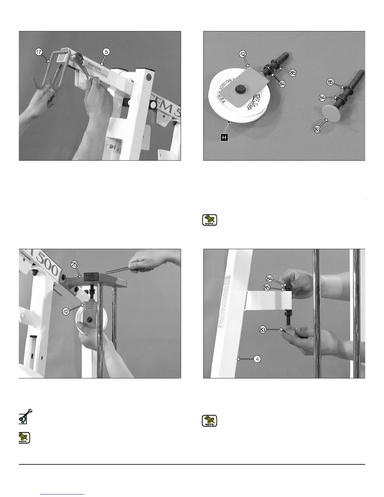
IG. 23 Insert the Lat Bar Holder (#17) into the tube-end of the Top
ulley Housing (#5), as shown above, and secure it into place using one
ex Head Cap Screw 3/8-16 X 2 1/2 (#44), two Flat Washers SAE 3/8
45) and one Nylon Insert Jam Lock Nut 3/8-16 (#48).
FIG. 26 Insert (from bottom to top) the Adjustable Stopper (#83) int
the receptacle of the Front Upright (#4) and secure it into place usin
one Split Washer B.O. 1/2 (#85) and one Regular Hex Nut 1/2-13 (#84
as shown above. Loosely fasten the Regular Hex Nuts 1/2-13 (#84) t
allow adjustment for cable tension later in the assembly process.
Note: Refer to Fig. 57 on page 19 for further clarification of thi
assembly.
Fig. 24 Assemble the Adjustable Pulley Bracket (#42) using on
Nylon Pulley 4 1/2 Rd. (#26-Labeled H), one Hex Head Cap Screw 3/8-1
X 1 3/4 (#50), two Flat Washers SAE 3/8 (#45) and one Nylon Insert Ja
Lock Nut 3/8-16 (#48). Next, thread a Regular Hex Nut 1/2-13 (#84) an
insert one Split Washer B.O. 1/2 (#85) onto the welded Hex Tap Bolt.
Next, locate the Adjustable Stopper (#83) then thread a Regular Hex N
1/2-13 (#84) and insert one Split Washer B.O. 1/2 (#85) onto the welde
Hex Tap Bolt.
Note: The black boxed letters pointing to the pulleys are us
throughout this manual as reference to the Cable Mapping Diagra
on page 16. These black boxed letters will be primarily used f
locating certain pulleys during the cable routing process beginnin
with Fig. 27.
IG. 25 Attach the Adjustable Pulley Bracket (#42) through he hole
cated on the Guide Rod Retainer Housing (#25) and secure it into
ace at the top using one Flat Washer SAE 1/2” (#59) and one Nylon In-
rt Jam Lock Nut 1/2-13 (#58).
Loosely Fasten: Do not completely fasten this hardware assem-
bly at this time, as it will be completely fastened later in the as-
sembly process.
Note: Refer to Fig. 56 on page 19 for further clarification of this
assembly.
FM-500 Compact Frontal Machine
8
wner
s
anua
:
ssem
y
ns
ruc
on
SELY FASTEN