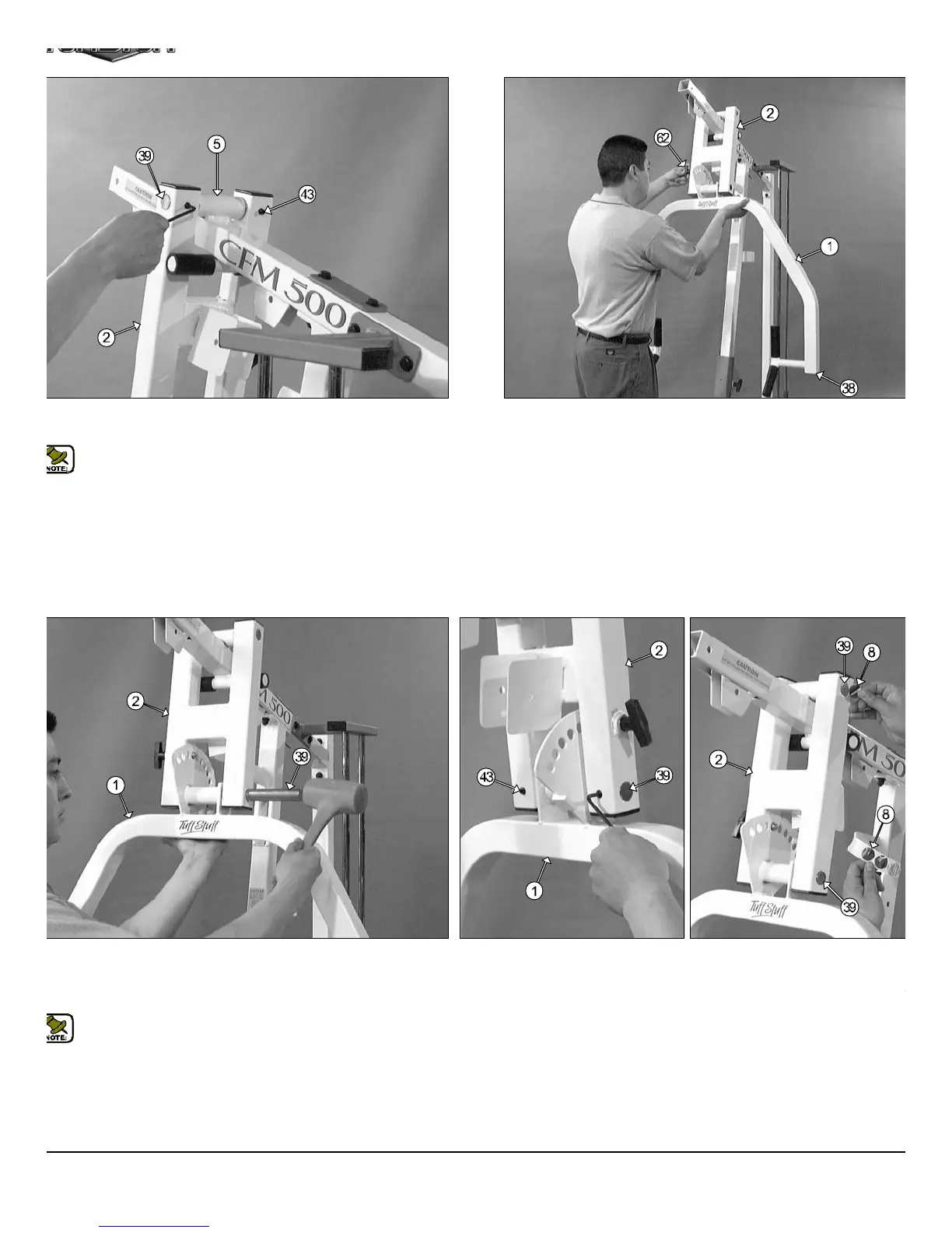
IG. 19 Secure the Press Bar Selector Housing (#2) to the Pivot
xle (#39) using two set screws 3/8-16 X 1/2 (#43).
Note:Use the supplied Hex Key 3/16 (#79) for securing the Set
Screws 3/8-16 X 1/2 (#43) into the threaded sockets located on the
Press Bar Selector Housing (#2).
FIG. 20 Next, using a rubber mallet, insert two Plastic Insert Caps
Sq. (#38-Not shown) into the tube-ends of the Press Bar (#1). Nex
insert the Press Bar (#1) up into the Press Bar Selector Housing (#
and support it into place using the push-pull pin (#62), as shown above.
IG. 21 Next, insert the Pivot Axle 1 X 8 1/8 (#39) into the Press Bar
elector Housing (#2) and through the Press Arm (#1) until it is flush
ith both sides to the Press Bar Selector Housing (#2).Refer to Fig. 53
page 18 for further clarification of this assembly.
Note: It is recommended to grease the Pivot Axle 1 X 8 1/8 (#39)
with multi-purpose grease prior to assembling.
FIG. 22 Secure the Press Bar (#1) into the Press Bar Selector Hou
ing (#2) by threading the two Set Screws 3/8-16 X 1/2 (#43) against th
Pivot Axle (#39) using the supplied Hex Key 3/16 (#79).
Next, apply four 1" Rd. Silver Mylar Decals (#8) over each end of the tw
Pivot Axles (#39). These Decals are used to hide and protect the ends
the Pivot Axles (#39).
CFM-500 Compact Frontal Machin
7