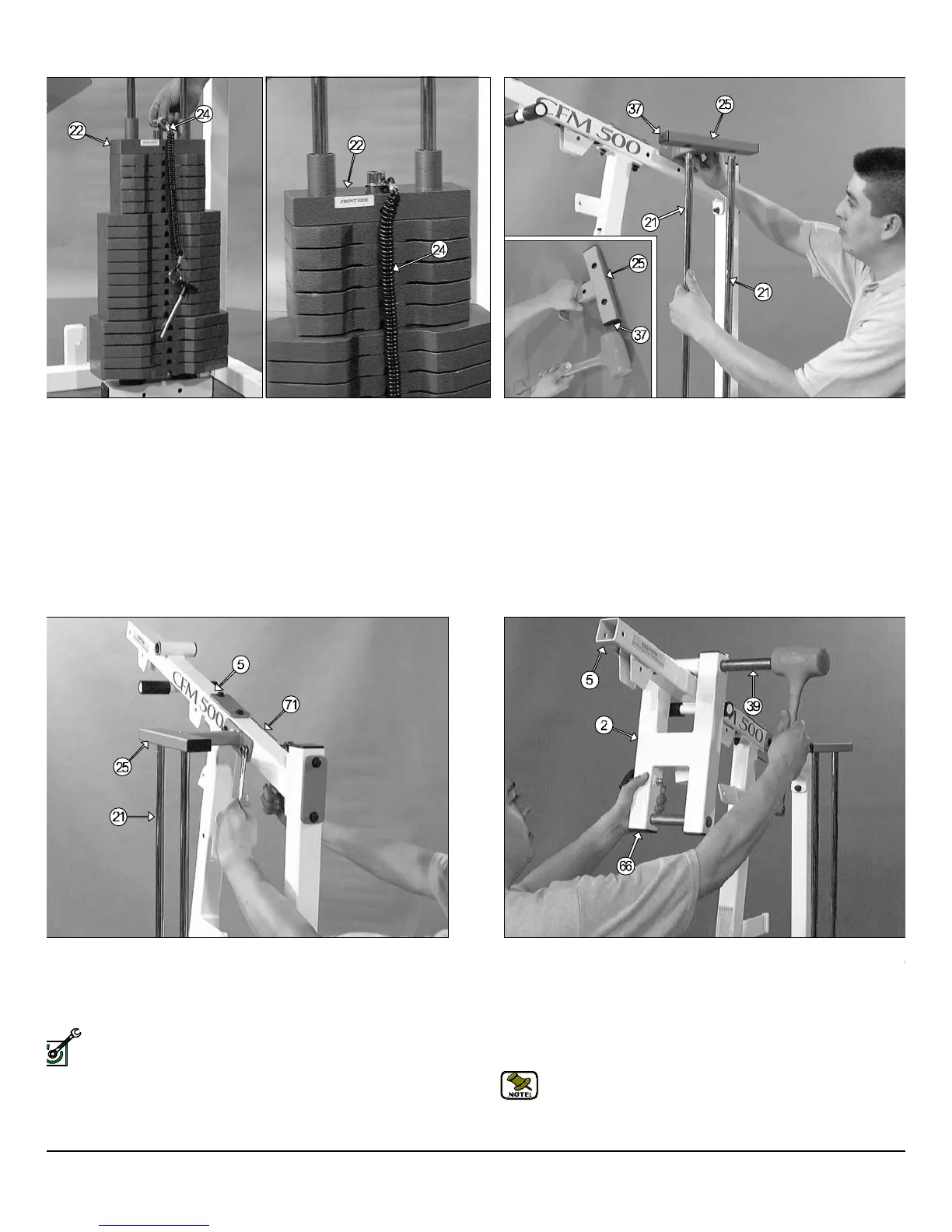
FIG. 16 Next, locate the Guide Rod Retainer Housing (#25) and, usin
a rubber mallet, insert two Plastic Insert Caps 1 X 2 ( #37) into the tub
ends, as shown in caption above. Maneuver each of the Guide Ro
(#21) into the holes located on the bottom side of the Guide Ro
Retainer Housing (#25).
FIG. 18 The two Pivot Axles 1 X 8 1/8 (#39) have been pr
assembled to the Press Bar Selector Housing (#2). Use the supplie
Hex Key 3/16" (#79) to loosen the Set Screws 3.8-16 X 1/2 (#43) that hol
the Pivot Axles 1 X 8 1/8 (#39) into place. Next, at tach the Press B
Selector Housing (#2) to the Top Pulley Housing (#5) and, using a ru
ber mallet, insert the Pivot Axles 1 X 8 1/8 (#39) through the holes in th
Press Bar Selector Housing (#2) and through the receptacle of the To
Pulley Housing (#5) until it is flush with both sides.
Note: It is recommended to grease the Pivot Axle 1 X 8 1/8 (#3
with multi-purpose grease prior to assembling. Also, the four Pla
tic Insert Caps 2" Sq. (#66) located in the tube-ends of the Pre
Bar Selector Housing (#17) have been pre-assembled by the fa
tory.
IG. 15 Next, locate the Selector Pin w/Coil (#24) and attach it to the
op Plate Selector Bar (#22) as shown above.
IG. 17 Mount the Guide Rod Retainer Housing (#25) along with the
o captive Guide Rods (#21) to the side of the Top Pulley Housing (#5)
d secure them into place using one Support Plate 1/4 X 2 X 5 (#71),
o Hex Head Cap Screws 3/8-16 X 3 1/4 (#49), four Flat Washers SAE
8 (#45) and two Nylon Insert Lock Nuts 3/8-16 (#51).
Fully Fasten: Proceed to align and fully fasten this hardware
assembly and all the previous assemblies that were left loosely
fastened. (Assemblies described in Fig.6, Fig. 7, Fig.8, Fig. 10 and
Fig.11).
FM-500 Compact Frontal Machine
6
wner
s
anua
:
ssem
y
ns
ruc
on
LY FASTEN