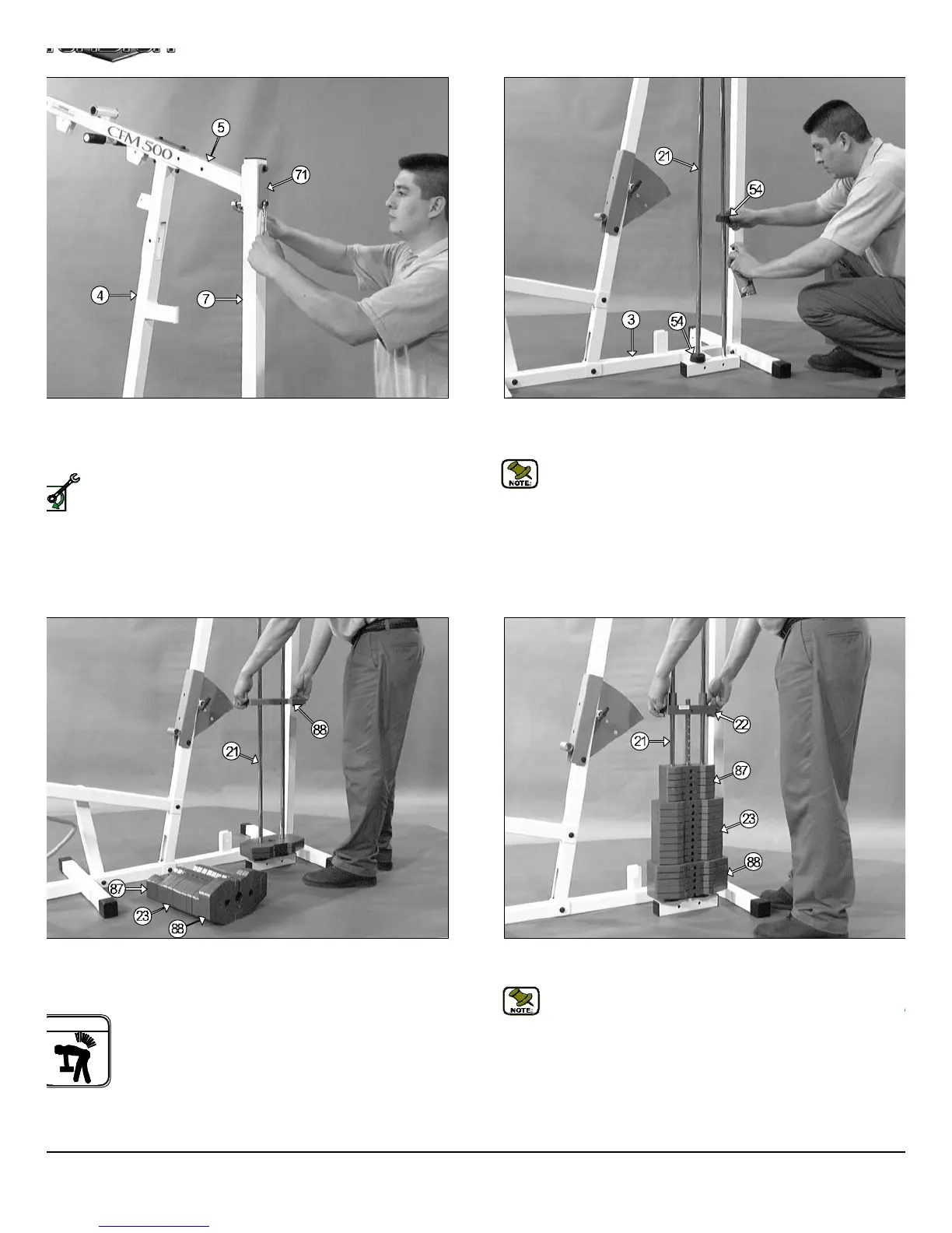
FIG. 14 Now slide the Top Plate/ Selector Bar (#22) over the Guid
Rods (#21) allowing it to come to rest on the completed weight stack.
Note: Be sure the label (FRONT SIDE) located on the Top Plat
Selector Bar (#22) is facing toward you before you slide the To
Plate/ Selector Bar (#22) over the Guide Rods 3/4 X 72 (#21).
IG. 11 Attach the Top Pulley Housing (#5) to the Rear Upright (#7)
d secure it into place using one Support Plate 1/4 X 2 X 5 (#71), two
ex Head Cap Screws 3/8-16 X 3 1/4 (#49), four Flat Washers SAE 3/8
45) and two Nylon Insert Lock Nuts 3/8-16 (#51).
Loosely Fasten: Do not completely fasten this hardware
assembly at this time, as it will be completely fastened later in the
assembly process.
FIG. 12 Insert the two Guide Rods 3/4 X 72 (#21) into the receptacl
located on the Base Frame (#3), as shown above. Slide two Rubb
Donuts 3/4 X 2 1/2 (#54) onto each Guide Rod 3/4 X 72 (#21), as shown
Note: Lubricate the Guide Rods 3/4 X 72 (#21) with silicone
teflon lubricant before proceeding.
IG. 13 Carefully begin sliding the Weight Plates over the Guide
ods (#21) beginning with the five 15 Lb. Weight Plates (#88) at the bot-
m, the nine 10 Lb. Weight Plates (#23) in the middle and the five 5 Lb.
eight Plate (#87).
Warning: Do not lift more than you can control safely. In
addition, do not lift using only your back. It is recommended
that when you are lifting, bend your knees and lift slowly with
your back straight. Be sure that the weight is distributed
over your knees or legs when lifting. Also, it is advisable to
wear a well fitted lifting belt during heavy lifting.
CFM-500 Compact Frontal Machin
5
SELY FASTEN
ARNING