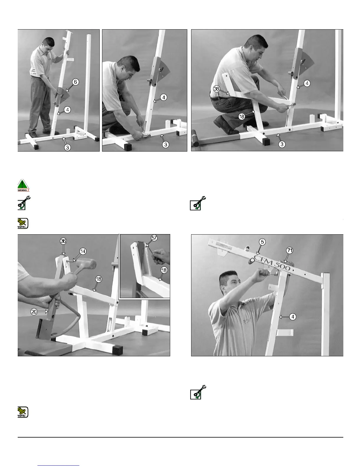
FIG. 10 Attach the Top Pulley Housing (#5) to the Front Uprig
(#4) and secure it into place using one Support Plate 1/4 X 2 X 5 (#71
two Hex Head Cap Screws 3/8-16 X 3 1/4 (#49), four Flat Washers SA
3/8 (#45) and two Nylon Insert Lock Nuts 3/8-16 (#51).
Loosely Fasten: Do not completely fasten this hardwa
assembly at this time, as it will be completely fastened later in t
assembly process.
IG. 7 Attach the Front Upright (#4) to the Base Frame (#3) and
cure it into place using one Hex Head Cap Screw 3/3-16 X 2 3/4 (#47),
o Flat Washers SAE 3/8 (#45) and one Nylon Insert Jam Lock Nut 3/8-
(#48).
Warning: This procedure requires the assistance of another per-
son.
Loosely Fasten: Do not completely fasten this hardware
assembly at this time, as it will be completely fastened later in the
assembly process.
Note: The Back Pad Bracket (#6) has been pre-assembled to the
Front Upright (#4) by the factory.
FIG. 8 Attach the Leg Extension Bench Frame (#18) to the Bas
Frame (#3) and secure it into place using one Hex Head Cap Screw 3/
16 X 4 1/2 (#53), two Flat Washers SAE (#45) and one Nylon Insert Ja
Lock Nut 3/8-16 (#48). Next, attach the Leg Extension Bench Fram
(#18) to the Front Upright (#4) and secure it into place using one He
Head Cap Screw 3/8-16 X 2 3/4 (#47), two Flat Washers SAE 3/8 (4
and one Nylon Insert Jam Lock Nut 3/8-16 (#48).
Loosely Fasten: Do not completely fasten this hardwa
assembly at this time, as it will be completely fastened later in th
assembly process.
Next, insert one Plastic Insert Cap 2” Sq. (#38) into the front of the Le
Extension Bench Frame (#18).
IG. 9 Affix the Leg Extension Arm (#20), in the position as shown, to
e Leg Extension Bench Frame (#18) and secure it into place using the
eg Extension Axle 1/2 X 2 1/2 (#14). Next, secure the Leg Extension
xle 1/2 X 2 1/2 (#14) into place using two Set Screws 1/4-20 X 3/8 (#57),
shown in caption above. Use the supplied Hex Key 1/8 (#77) for
stening these Set Screws 1/4-20 X 3/8 (#57). Next, insert one Plastic
sert Cap 1 1/2 Sq. (#36) into the tube-end of the Leg Extension Arm
20).
Note: It is recommended to grease the Leg Extension Axle 1/2 X
2 1/2 (#14) with multi-purpose grease prior to assembling.
FM-500 Compact Frontal Machine
4
wner
s
anua
:
ssem
y
ns
ruc
on
SELY FASTEN
LOOSELY FASTEN
LOOSELY FASTEN