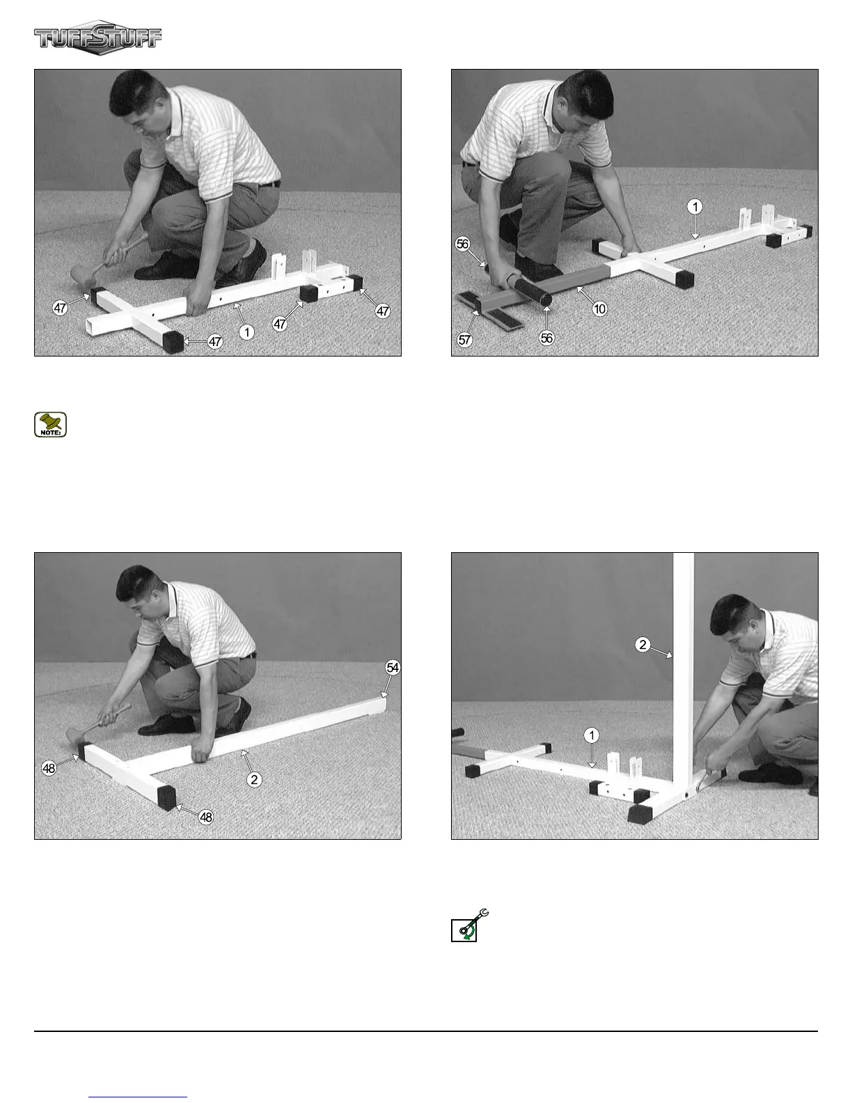
FIG. 4 On a flat surface, lay the Base Frame (#1) down and insert four
Plastic End Caps w/Groove 2” Sq. (#47) onto the tube-ends of the Base
Frame (#), as shown above.
Note: When positioning the Base Frame (#1) consider the
complete area surface of the CFM-550. Use the overhead view on
the cover page for designing your layout before assembling.
FIG. 5 Next, locate the Low Row Foot Assembly (#10) and, using a
rubber mallet, insert two Plastic End Caps 2” Rd. (#56) and one Plastic
Insert Cap 1-3/4 Sq. (#57) into the tube-ends. Next, slide the Low Row
Foot Assembly (#10) into the receptacle of the Base Frame (#1), as
shown above.
FIG. 6 Next, locate the Rear Upright (#2) and, using a rubber mallet,
insert one Plastic Insert Cap 2 X 3 (#54) into the tube-end. Next, insert
two Plastic End Caps w/Groove 2 X 3 (#48) onto the stabilizer of the Rear
Upright (#2), as shown above.
FIG. 7 Attach the Rear Upright (#2) to the Base Frame (#1) and
secure it into place using two Hex Head Cap Screws 3/8-16 X 4-1/4 (#77),
four Flat Washers SAE 3/8” (#60), and two Nylon Insert Lock Nuts 3/8-16
(#69).
Loosely Fasten: Do not completely fasten this hardware
assembly at this time, as it will be completely fastened later in the
assembly process.
LOOSELY FASTEN
CFM-550 Compact Frontal Machine
3