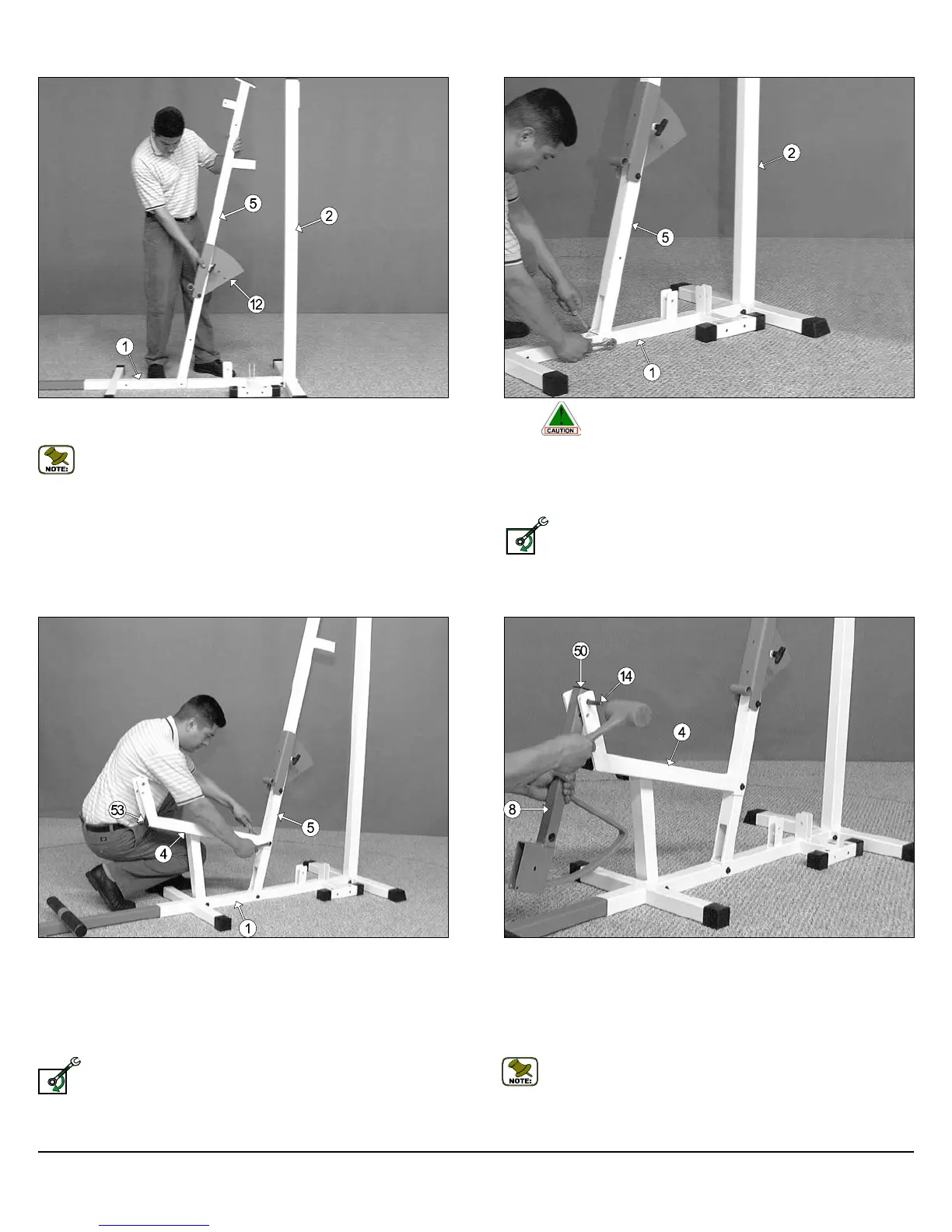
FIG. 10 Attach the Leg Extension Bench Frame (#4) to the Base
Frame (#1) and secure it into place using one Hex Head Cap Screw 3/8-
16 X 4-1/2 (#78), two Flat Washers SAE 3/8” (#60), and one Nylon Insert
Jam Lock Nut 3/8-16 (#68). Next, attach the Leg Extension Bench
Frame (#4) to the Front Upright (#5) and secure it into place using one
Hex Head Cap Screw 3/8-16 X 2-3/4 (#75), two Flat Washers SAE
3/8” (60), and one Nylon Insert Jam Lock Nut 3/8-16 (#68).
Loosely Fasten: Do not completely fasten this hardware
assembly at this time, as it will be completely fastened later in the
assembly process.
Next, using a rubber mallet, insert one Plastic Insert Cap 2” Sq. (#53) into
the front of the Leg Extension Bench Frame (#4).
FIG. 9 Caution: It is recommended to use another person in as-
sisting with this assembly.
Attach the Front Upright (#5) to the Base Frame (#1) and secure it into
place using one Hex Head Cap Screw 3/8-16 X 2-3/4 (#75), two Flat
Washers SAE 3/8” (#60), and one Nylon Insert Jam Lock Nut 3/8-16
(#68).
Loosely Fasten: Do not completely fasten this hardware
assembly at this time, as it will be completely fastened later in
the assembly process.
Owner’s Manual: Assembly Instructions
FIG. 11 Locate the Leg Extension Arm (#8), and using a rubber mal-
let, insert one Plastic Insert Cap 1-1/2 Sq. (#50) into the tube-end.
Next, affix the Leg Extension Arm (#8), in the position as shown above,
to the Leg Extension Bench Frame (#4) and secure it into place by in-
serting the Leg Extension Axle 1/2 X 2-3/4 (#14) through the Leg
Extension Bench Frame (#4) and Leg Extension Arm (#8) until it be-
comes flush with both sides of the Leg Extension Bench Frame (#4).
Note: It is recommended to grease the Leg Extension Axle 1/2 X
2-3/4 (#14) with multi-purpose grease prior to assembling.
FIG. 8 This picture depicts the position of the Front Upright (#5), and
where it is going to be assembled on the Base Frame (#1).
Note: The Back Pad Bracket (#12) has been pre-assembled to the
Front Upright (#5) by the factory.
4
CFM-550 Compact Frontal Machine
LOOSELY FASTEN
LOOSELY FASTEN