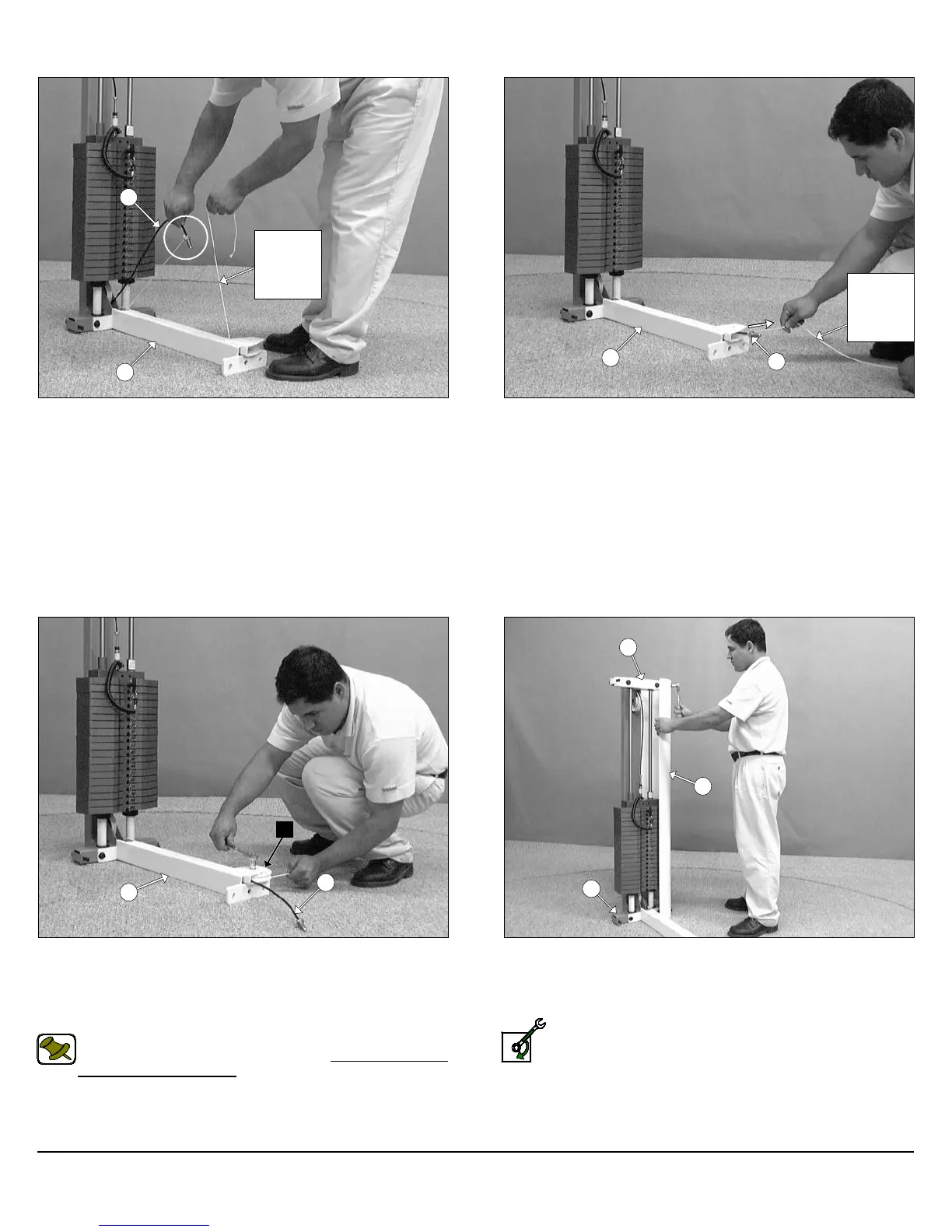
FIG. 11 Attach a Nylon Pulley 4 1/2” Rd. (#16-Labeled C) to the
Bottom Cross Brace (#38), in the position as shown above, and se-
cure it into place using one Hex Head Cap Screw 3/8-16 X 1 3/4
(#27), two Flat Washers SAE 3/8” (#19), and one Nylon Insert Jam
Lock Nut 3/8-16 (#23).
Note: The black boxed letter pointing to the pulleys are used
throughout this manual as reference to the Cable Mapping Dia-
gram on fold-out page 10. These black boxed letters will be
primarily used for locating certain pulleys during the cable rout-
ing process beginning with Fig. 11.
FIG. 12 Affix the Weight Shroud w/Plate (#3) to the bottom of the
Weight Stack Frame (#1) and at the top of the Guide Rod Retainer
(#5) using four Hex Head Cap Screws 1/4-20 X 3/4 (#21), and four
Flat Washers 1/4” (#20).
Loosely Fasten: Do not completely fasten this hardware as-
sembly at this time, as it will be completely fastened later in
the assembly process.
FIG. 9 To facilitate the routing of the Cable (#87) through the Bot-
tom Cross Brace (#38) use the supplied Cable Fishing String. Tie a
knot to the end of the Cable (#87) as shown above.
FIG. 10 Pull the Cable Fishing String along with the Cable (#87)
through the Bottom Cross Brace (#38) as shown above. Discard
the cable fishing string once completed with this process.
Owner’s Manual: Assembly Instructions
4
SP-403 Multi-Press
Cable
Fishing
String
38
87
38
87
Cable
Fishing
String
87
38
C
3
5
1