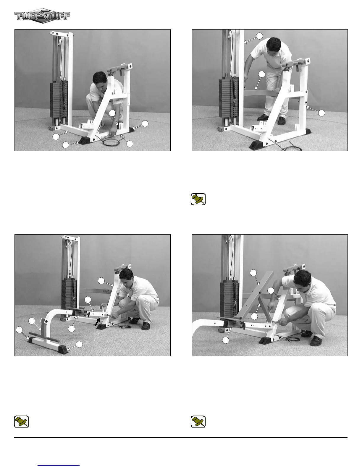
FIG. 15 Using a rubber mallet, insert two Plastic End Caps w/
Groove 2” Sq. (#52) onto the tube-ends of the Bench Main Frame
(#40). Insert the tube-end of the Bench Main Frame (#40) into the
receptacle of the Press Bar Main Frame (#32) and secure it into
place using two Hex Head Cap Screws 3/8-16 X 3 (#77), four Flat
Washers SAE 3/8” (#19), and two Nylon Insert Lock Nuts 3/8-16
(#30). Reinforce this assembly in the position indicated by the black
arrow using one Hex Head Cap Screw 3/8-16 X 1 (#74), and one Flat
Washer SAE 3/8” (#19).
Note: Refer to the Exploded View Diagram on fold- out page 11
for further illustration of this assembly.
FIG. 16 Attach the Bench Back Pad Frame (#36), in the position
as shown above, to the Bench Slide Carriage (#42) using one Hex
Head Cap Screw 1/2-13 X 4 1/2 (#83), two Flat Washers SAE
1/2” (#29), and one Nylon Insert Lock Nut 1/2-13 (#22). Next, attach
the Bench Support Bar (#37) to the Press Bar Main Frame (#32)
using one Hex Head Cap Screw 1/2-13 X 3 1/2 (#24), two Flat Wash-
ers SAE 1/2” (#29), and one Nylon Insert Jam Lock Nut 1/2-13 (#85).
Do not over-tighten these assemblies to allow free movement during
the use of the adjustment mechanism.
Note: Refer to the Exploded View Diagram on fold- out page 11
for further illustration of this assembly.
5
SP-403 Multi-Press
FIG. 13 Using a rubber mallet, insert two Plastic End Caps 2 X 3
(#53) onto the tube-ends of the Press Bar Main Frame (#32). Next,
attach the Press Bar Main Frame (#32) to the Bottom Cross Brace
(#38), in the position as shown above, and secure it into place using
two Hex Head Cap Screws 1/2-13 X 4 3/4 (#84), four Flat Washers
SAE 1/2” (#29), and two Nylon Insert Lock Nuts 1/2-13 (#22).
FIG. 14 Affix the Rear Cross Brace (#39) to the Press Bar Main
Frame (#32) using two Hex Head Cap Screws 1/2-13 X 4 3/4 (#84),
four Flat Washers SAE 1/2” (#29), and two Nylon Insert Lock Nuts
1/2-13 (#22). Next, connect the Rear Cross Brace (#39) to the
Weight Shroud w/Plate (#3) using two Hex Head Cap Screws 1/2-13
X 1 (#80), and two Split Lock Washers B/O 1/2” (#62).
Note: Refer to the Exploded View Diagram on fold- out page 11
for further illustration of this assembly.
53
32
38
53
53
32
39
3
32
40
42
41
42
36
37
32
52
52