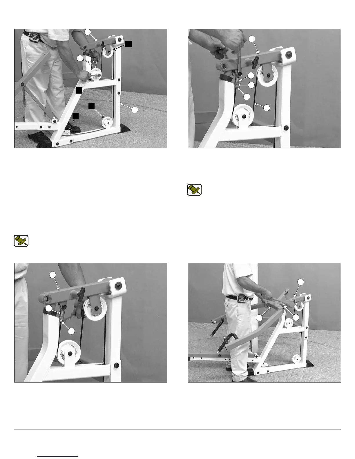
FIG. 17 Route the Cable (#87) under the Nylon Pulley 4 1/2 Rd.
(#16-Labeled D) and attach it to the Press Bar Main Frame (#32)
pulley bracket using one Hex Head Cap Screw 3/8-16 X 2 (#26), two
Flat Washers SAE 3/8” (#19), and one Nylon Insert Jam Lock Nut 3/8-
16 (#23). Continue routing the Cable up through the opening on the
Press Bar Main Frame (#32). Next, route the cable over a Nylon
Pulley 4 1/2 Rd. (#16-Labeled E) and attach it to the Press Pivot
Arm (#33) pulley bracket using one Hex Head Cap Screw 3/8-16 X 2
(#26), two Flat Washers SAE 3/8” (#19), and one Nylon Insert Jam
Lock Nut 3/8-16 (#23). Next, route the cable under a Nylon Pulley 4
1/2 Rd. (#16-Labeled F) and attach it to the Press Bar Main Frame
(#32) pulley bracket using one Hex Head Cap Screw 3/8-16 X 2
(#26), two Flat Washers SAE 3/8” (#19), and one Nylon Insert Jam
Lock Nut 3/8-16 (#23).
Note: Refer to Cable Mapping Diagram on fold-out page 10
for further illustration of this assembly.
FIG. 18 Insert a Split Lock Washer Z/P 1/2” (#66) to the Cable Hex
Bolt 1/2-20 X 1 (#90) then thread the Rod End 1/2-20 (#89) to the Ca-
ble Hex Bolt 1/2-20 X 1 (#90). Next, affix the Rod End 1/2-20 (#89) to
the Press Bar Pivot Arm (#33) using one Hex Head Cap Screw 1/2-
13 X 1 1/2 (#81), and one Nylon Insert Jam Lock Nut 1/2-13 (#85).
Note: Refer to Fig B on fold-out page 10 for further detailed il-
lustration of this assembly.
Owner’s Manual: Assembly Instructions
FIG. 19 Fully fasten the Cable Bolt 1/2-20 X 1 (#90) to the Rod End
1/2-20 (#89).
FIG. 20 Attach the Press Bar (#31) to the Press Bar Pivot Arm
(#33), in the position as shown above. Next, Using a rubber mallet,
insert the Press Bar Pivot Axle (#34) through the receptacles of the
Press Bar (#31) and the receptacle of the Press Bar Pivot Arm
(#33) until it becomes flush with both sides of the Press Bar (#31).
6
SP-403 Multi-Press
C
D
E
F
32
87
33
33
89
66
87
90
33
90
89
33
35
31