user manual
FLEX ARRAY
FLEX ARRAY user manual
Page 36
Turning the drive nut on the end of the shaft tilts the load by varying the position of the
motor connection point relative to the centre of mass of the loudspeaker column. The lift
point position can be altered even when under load in order to obtain the desired final cluster
inclination.
The flybar‟s rear spine is provided with multiple locating holes along its length based on a
vernier scale adjustment. A captive 100mm (4”) ball-lock pin is used to lock the lift point‟s
position when one of the two holes in the lift point aligns with a fly bar locating hole.
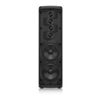
Floating drop links at each end of the box section engage into the flygear of the TFA-600H
mid/high cabinet or TFA-600L low frequency cabinet, and are secured with captive 15mm
(5/8”) ball-lock pins.
Two cabinet connection drop link positions are provided at the rear of the flybar at the
correct spacing for attachment to either TFA-600L low frequency cabinets or TFA-600H
mid/highs.
The net weight of the FB-600 flybar is 25 kgs.
Important Safety Notes
To ensure continued safe operation of the FB-600 flybar the following points should be noted:
The BLP-10/100 100mm (4”) locking pin should always be fitted to lock the lift point
before lifting the flybar
Four ball-lock pins must be fitted to ensure the safe lifting of the cluster
Under no circumstances should hands be placed in the open top of the spine when the
flybar is in use
Two safety lug points are provided for attaching wire safety rope. No other part of the
flybar can be used for this purpose
Any components that are damaged should be repaired or replaced by qualified service
personnel only
In the extremely unlikely event of failure of the screw the safety and operation of the
flybar is not compromised
 Loading...
